
You are using an out of date browser. It may not display this or other websites correctly.
You should upgrade or use an alternative browser.
You should upgrade or use an alternative browser.
An obscene use of titanium
- Thread starter JamesCH
- Start date
so if i move the threaded hole down I will shorten the throw?
If you move the threaded hole further from the 2 8mm holes (down in the drawing) you will shorten the throw even further, but the rubber boot on the shifter cable will start rubbing on stuff as you shift which will wreck it very quickly. If you move it towards the two holes (up) the throw will increase and the shifting force will go down.
If you move the hole left or right as it's printed in the drawing that will change the North/South position of neutral in the cabin.
perfect...!
perfect...!
Rock on, post up when you get it done and let me know how it works out for you!
GI thread started, if you're interested sign up on this thread:
http://www.mazdas247.com/forum/showthread.php?p=4850245#post4850245
http://www.mazdas247.com/forum/showthread.php?p=4850245#post4850245
- :
- 2007 MS3
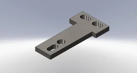
How about something like this? With the right dimensions, it could provide a little adjustability.
I like the idea, I have attached a quick model of something that could work. You'd need a nut on the back of the ball-stud, but the throw would be adjustable and the position of neutral has 3 selectable locations.
Attachments
- :
- 06 LS MS6
07 BM GT (shell has been struck from the roll)
So my question is why would you use titanium for this application? Stainless steel would seem like a much better choice if you are looking for a non-corroding material. Titanium is known for its light weight - which if you are making a "weight" just does not make sense.....
This is like mountain climbing, he made it because he could.
I made cylinder head bolt washers for my bike outtta Ti, just because
serious ly though, 1/2 plate?
lots of it ?
I got that aluminum STS plate that I made bolted up today with the help of some longer bolts from the hardware store and I found an interference issue. When shifting back into any even gear the very end of the STS plate hits part of the shifting mechanism. Fortunately this is a "material away" fix, accomplished by a relatively big chamfer on the bottom right corner of the STS plate (based on my drawing) or shaving about 0.25" off of the narrow end of the STS plate (the bottom end in my drawing).
I'll work out the clearances tomorrow and update my drawing.
I'll work out the clearances tomorrow and update my drawing.
This is like mountain climbing, he made it because he could.
I made cylinder head bolt washers for my bike outtta Ti, just because
serious ly though, 1/2 plate?
lots of it ?
Yes, a big pile of it actually, haha.
Drawing Fixed
Post #30 has been updated with a revised drawing that solves the clearance problem. Here it is again though. It only removes 0.250" from the narrow end of the plate, so if you had already made one you need only trim some material off.
Post #30 has been updated with a revised drawing that solves the clearance problem. Here it is again though. It only removes 0.250" from the narrow end of the plate, so if you had already made one you need only trim some material off.
Attachments
Last edited:
- :
- 2007 MS3
Post #30 has been updated with a revised drawing that solves the clearance problem. Here it is again though. It only removes 0.250" from the narrow end of the plate, so if you had already made one you need only trim some material off.
Your design looks as if it removes all the extra travel from the rearward motion of the shifter, whereas I want to keep the shifter towards the back of the car. Ideally I need 2,4 and 6 to be exactly where they are in stock form. I have long legs, so the seat is all the way back. In fact, one of these days I`m going to take it apart and figure out how to shift it back another inch or two on the rails.
Now that would be another (hopefully) cheap mod a lot of us would appreciate.
Darth Vader
Member
With my plate design, there is enough material to place the shifter wherever you like. You have to move the pivot ball forward from the location on my plan and, you might want to trim a bit off the back side of the plate, to avoid fouling the cable on the rear edge.
Your design looks as if it removes all the extra travel from the rearward motion of the shifter, whereas I want to keep the shifter towards the back of the car. Ideally I need 2,4 and 6 to be exactly where they are in stock form. I have long legs, so the seat is all the way back. In fact, one of these days I`m going to take it apart and figure out how to shift it back another inch or two on the rails.
Now that would be another (hopefully) cheap mod a lot of us would appreciate.
If that's your goal I would recommend moving the threaded hole a little bit to the right in the drawing. This will push the location of neutral back (south) inside the cabin. If you want a slightly longer throw, move it up in the drawing.
The left-right distance between the clearance hole center (stock mounting point) and the threaded hole will be multiplied 2x-3x in the cabin. That is to say if you move the threaded hole 1/4" to the right of the clearance hole, "neutral" in the cabin will be pushed back 1/2"-3/4". You may want to make the plate wider to be able to move the threaded hole as far back as you'd like. Make sense? It's a little hard to explain...
Wagonbacker9
Member
- :
- 2004 'Hoe
If that's your goal I would recommend moving the threaded hole a little bit to the right in the drawing. This will push the location of neutral back (south) inside the cabin. If you want a slightly longer throw, move it up in the drawing.
The left-right distance between the clearance hole center (stock mounting point) and the threaded hole will be multiplied 2x-3x in the cabin. That is to say if you move the threaded hole 1/4" to the right of the clearance hole, "neutral" in the cabin will be pushed back 1/2"-3/4". You may want to make the plate wider to be able to move the threaded hole as far back as you'd like. Make sense? It's a little hard to explain...
having never seen your shifter, and not being able to see your new shift plate at work, I understood. lol. give yourself some credit.
- :
- 2007 MS3
Make sense? It's a little hard to explain...
I appreciate the explanation, but remember I created my own drawing (crude as it was) and figured out from looking at yours how it would locate the shifter, so I clearly understand the leverage effect of moving the different holes.
It occurs to me that a properly designed plate might accommodate those who want the shift forward and those who want it rearward just by flipping it over. Of course this would leave the folks who want it left centered out in the cold, but nothing is perfect...
Wagonbacker9
Member
- :
- 2004 'Hoe
I appreciate the explanation, but remember I created my own drawing (crude as it was) and figured out from looking at yours how it would locate the shifter, so I clearly understand the leverage effect of moving the different holes.
It occurs to me that a properly designed plate might accommodate those who want the shift forward and those who want it rearward just by flipping it over. Of course this would leave the folks who want it left centered out in the cold, but nothing is perfect...
this would knock it down to 2 part drawings though... assuming it would work.. it may also be possible to make one where flipping it would move it from forward to centered... assuming I'm seeing the part drawing in my head correctly.
Fair enough. I suppose I'll add this: they key dimensions in my drawing are the three thru-holes, because they're on the stock setup and cannot be changed, every other dimension is merely a suggestion. Other than the thru-holes anyone can modify the profile or the location of the threaded hole for whatever they're aiming to do. I just wanted to supply the design tools that one would need to make their own custom STS plate and a baseline design that worked.
Wagonbacker9
Member
- :
- 2004 'Hoe
a little off topic, but has anyone looked into making a hood prop kit with mcmaster parts? this talk of ball studs has me thinking.
(hmm... that sounded a little gay..)
(hmm... that sounded a little gay..)
New Posts and Comments
- Replies
- 41
- Views
- 602

- Replies
- 9
- Views
- 1K

- Replies
- 10
- Views
- 2K
