
stickhunter
Member
- :
- 2006 Mazda 5 Sport
Hi all,
Like many, I've had troubles with aggressive wear on the inside edges of my 2006 Mazda 5's rear tires, so I decided to install some adjustable camber rear upper arms. I purchased these arms from RockAuto: ULTRA-POWER MS40125

At $30 each, they're hard to beat and are a clone of the more common SPC arms.
The arms arrived with no instructions, but I found the instructions from SPC: http://www.spcalignment.com/instructions/67420-INS_WEB.pdf
I had trouble finding any more information that described how the adjustment nuts worked, so I decided to put together this picture tutorial to show how I made the initial adjustments on the arms according to SPC's instructions. I hope this helps someone!
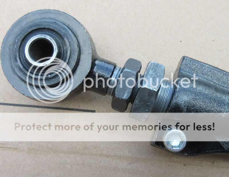
The first thing I did was to take apart the arms to clean and lubricate the threads. After loosening the allen-head pinch bolt, I mounted the arm in a vise and turned the larger adjuster nut counter-clockwise. This took considerable force to break loose as this arm had some corrosion on the threads.
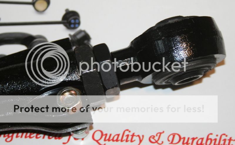


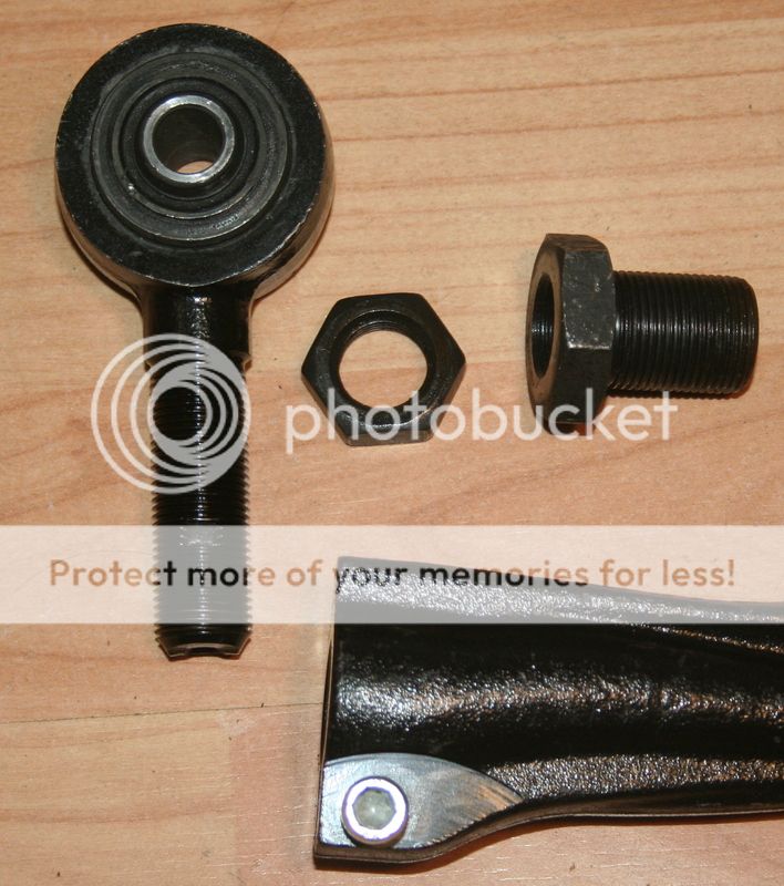
The adjuster nut is actually a hollow bolt into which the outer bushing is threaded along with a jam nut. These will come out as a unit.
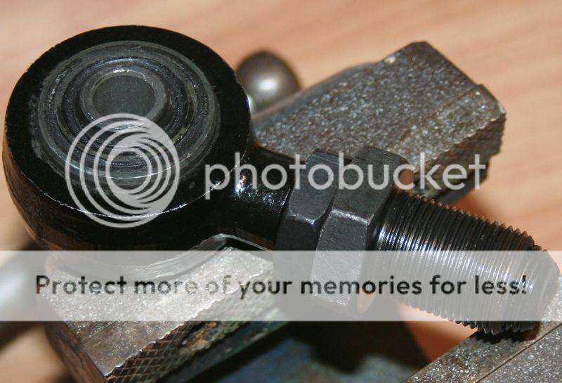
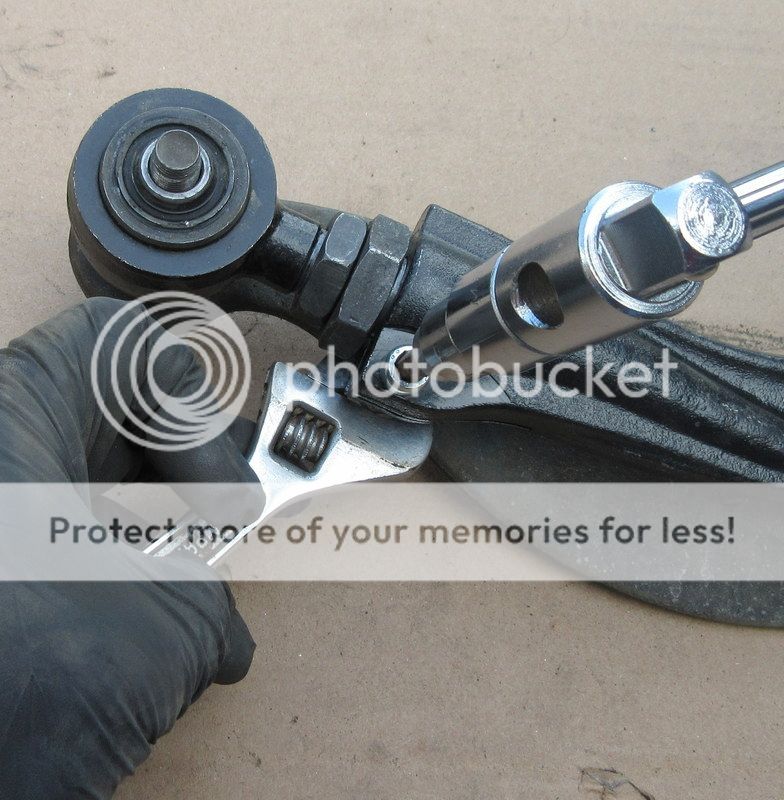
I then placed the adjuster nut in the vise and turned smaller jam nut clockwise to remove the outer bushing. This is important: the jam nut and outer bushing are threaded left-handed, so clockwise to loosen and counter-clockwise to tighten.

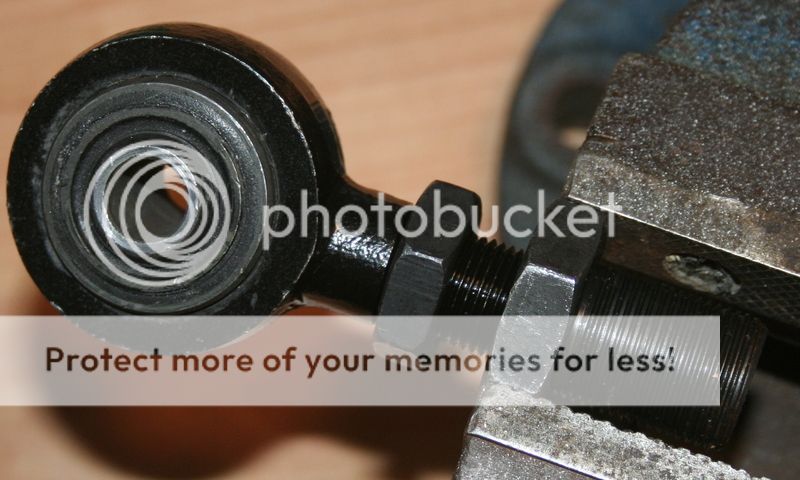
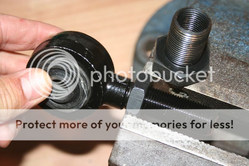
Finally, I mounted the jam nut in the vise and with my hand, turned the outer bushing clockwise to remove it from the jam nut.

With all the pieces apart, I cleaned the threads and applied some anti-seize. Don't forget the pinch bolt. I'm hoping this will make future adjustment easier.

I then re-assembled the upper arm according to SPC's instructions by threading the adjuster bolt fully into the arm (clockwise), the jam nut fully onto the outer bushing (counter-clockwise), and the outer bushing fully into the adjuster bolt (counter-clockwise). At this point, the pinch bolt is still loose.

I don't have my OEM arms out yet to set the initial dimensions, but the best instructions I've found are to lay the new arm over the original arm and use the mounting bolts to align both bushings. To adjust the arm to the initial length, place it in a vise and turn the adjuster nut counter-clockwise while keeping the outer bushing from rotating. The combination of right-hand and left-hand threads will cause the adjuster bolt and outer bushing (along with jam nut) to simultaneously extend exposing an even amount of threads on each side of the adjuster nut.


When the initial length is set, tighten the pinch bolt to 20 ft-lb and run the jam nut tight against the adjuster nut. Again, remember that the jam nut turns counter-clockwise to tighten.
Once the arm is installed, it should be possible to adjust the camber without removing the entire arm by loosening the pinch bolt and jam nut, and turning the adjuster nut counter-clockwise to increase camber and clockwise to reduce camber.
One thing to keep in mind is that the length of exposed threads should be the same on the adjuster bolt and the outer bushing, and should not exceed 1/2" lest you end up with not enough thread engagement.
Anyways, I hope these pictures help. I'll let you know how the final install goes.
NOTE: The following procedures describe how I installed the adjustable upper control arms on my 2006 Mazda 5, and may not be accurate for your model vehicle. These procedures describe what worked for me and do not necessarily represent the correct or best way to perform the installation. Of particular note, the 2006 Mazda 5 workshop manual describes a different procedure that involves removing the lower control arm and spring. The torque values given come from the 2006 Mazda 5 workshop manual, but please double-check with your own resources.
Passenger-side Installation
I started with the rear passenger side as this is the easier of the two sides. Begin by loosening the wheel lug nuts and raising the vehicle. Place a jack stand in a location that will not load the suspension (you need to be able to move the suspension freely). I placed mine under the front control link bracket.

Remove the wheel and place it under the vehicle as an emergency backup to the jack stand; you'll be laying or reaching under the vehicle, so make sure it is safely supported.

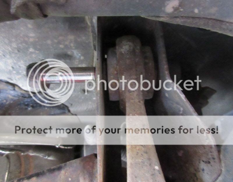
Locate the outer bolt that holds the upper control arm to the hub and the inner bolt that holds the upper control arm to the frame.


Using a 17mm socket, break loose both the outer and inner bolts. Mine were pretty easy to loosen.


Note the brake line bracket, which is also held by the outer bolt. Remove the outer bolt; the hub will drop away from the control arm.


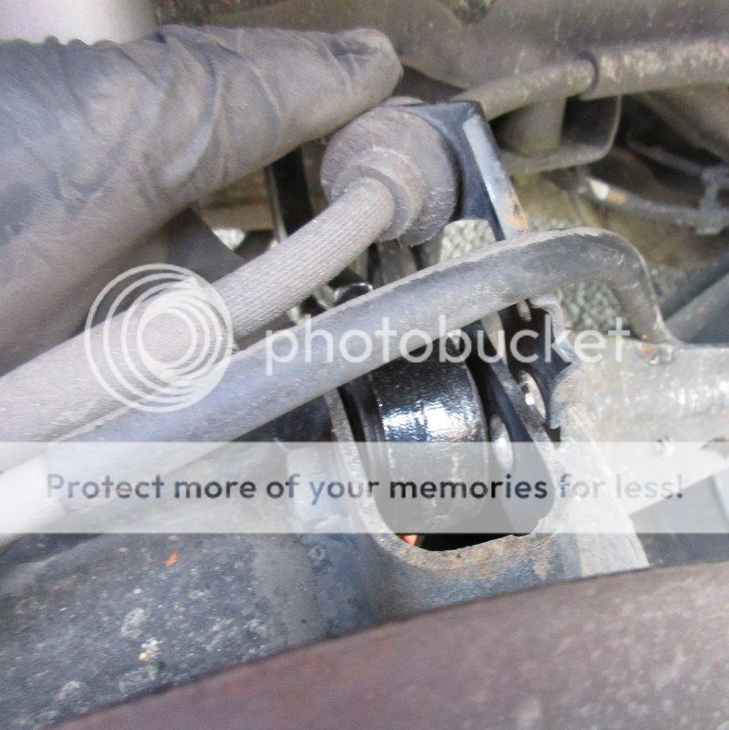
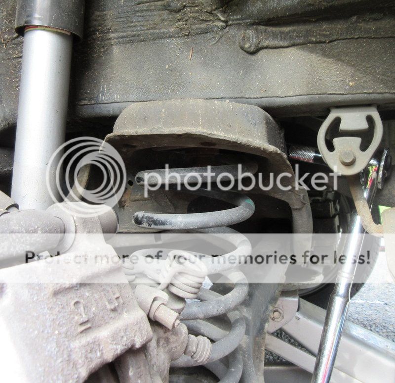
Remove the inner bolt by using a 12" extension to access it from behind the gas filler hose.
With both bolts removed, remove the upper control arm.

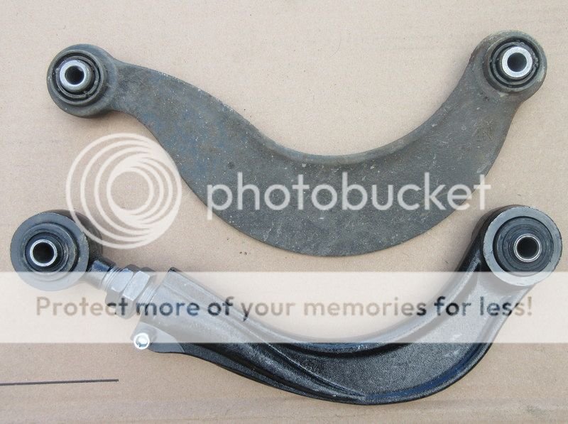
Here's the factory upper control arm beside the adjustable upper control arm.
Loosen the pinch bolt (counter-clockwise) and lock nut (clockwise) on the adjustable arm.
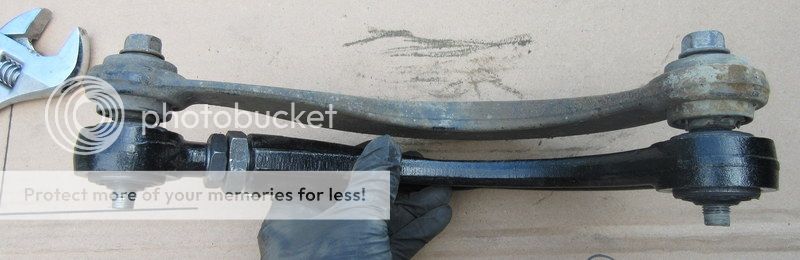
Using the inner bolt as a pin, align the fixed end of the adjustable arm with the factory arm. Adjust the length of the adjustable arm until the outer bolt can be used as a pin to align the other end of the arms. Increase length by turning the adjuster nut counter-clockwise while keeping the outer bushing from turning. The threads will evenly extend or retract on either side of the adjuster nut.

I set my arms to the original length since I plan to adjust them afterwards in-situ, but you could turn the adjuster nut 2 full turns (again, with the outer bushing held) to increase the camber. Anecdotal comments indicate that four 360 degree turns of the outer bushing from the factory length gets you in the ballpark of 0 degree camber. I halved this number since turning the adjuster nut extends the threads in both directions.
Once the length is set, tighten the pinch bolt (clockwise) to 20 ft-lbs and tighten the lock nut (counter-clockwise).

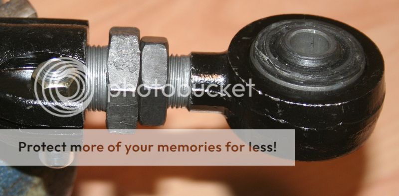
Note the grey (anti-seize) threads on either side of the adjuster and lock nuts. If the arm is properly adjusted, there should be an even length of threads on either side and these threads should not exceed 1/2". The threads beside the lock nut are critical; without them, the lock nut cannot be loosened to allow adjustment after the arm is installed.

Align the inner (non-adjustable) half of the arm with the frame bracket and loosely install the bolt (you want to keep the arm free to move).


Partially align the the outer half of the arm with the hub; the outer bushing will not fully-align until the suspension is raised.

Place a jack under the lower arm and raise the hub slightly to improve the vertical alignment of the outer bushing.

Push against the upper part of the rotor to move the hub into alignment with the upper arm bushing and then reinstall the bolt. Make sure to hand-tighten the bolt initially to prevent cross-threading and don't forget to install the brake line bracket.
Lower the jack to restore the suspension tension and then tighten the outer and inner bolts to between 66 and 90 ft-lbs.

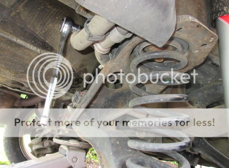
Here's the passenger side adjustable upper control arm after installation. There's pretty good access to the adjuster nut from behind the wheel. To adjust, while facing the car, loosen the pinch bolt (counter-clockwise) and lock nut (clockwise). Turn the adjuster nut clockwise to decrease camber and counter-clockwise to increase camber. Retighten the pinch bolt (clockwise) and lock nut (counter-clockwise) after adjustment.


Reinstall the wheel, lower the vehicle, and torque the lug nuts to 65 - 87 ft-lb.
Post-installation note:
After setting the initial length of the arm, leave the lock nut loose so that there is some rotational play in the outer bushing. This will make it easier to realign with the hub. After the bolt is installed, tighten the lock nut.
Driver-side Installation
On the driver side, the inner bolt is blocked by an exhaust hanger. In my first attempt, I repeated the same steps as described for the passenger side. Once I had the inner bolt loosened, I spent 45 minutes trying to angle and push the bolt under the exhaust hanger. I eventually gave up and removed the exhaust from the three rear-most hangers; this gave me enough clearance to easily remove and reinstall the inner bolt. In retrospect, I should have begun by lowering the exhaust, so this is how I will describe the procedure, but because I did not do this initially, some of the pictures show the exhaust raised.
Follow the procedure described for the passenger side install until the point that you are ready to remove the inner bolt. Use some dish soap to lubricate the rear-most exhaust hanger pin (by the muffler) and slide off the rubber hanger. You should be able to do this by hand after sliding the rubber back and forth on the pin a few times to spread the soap.
Use the same technique to remove the exhaust from the second rear-most hanger; this is the one that you see facing you from the rear wheel well.

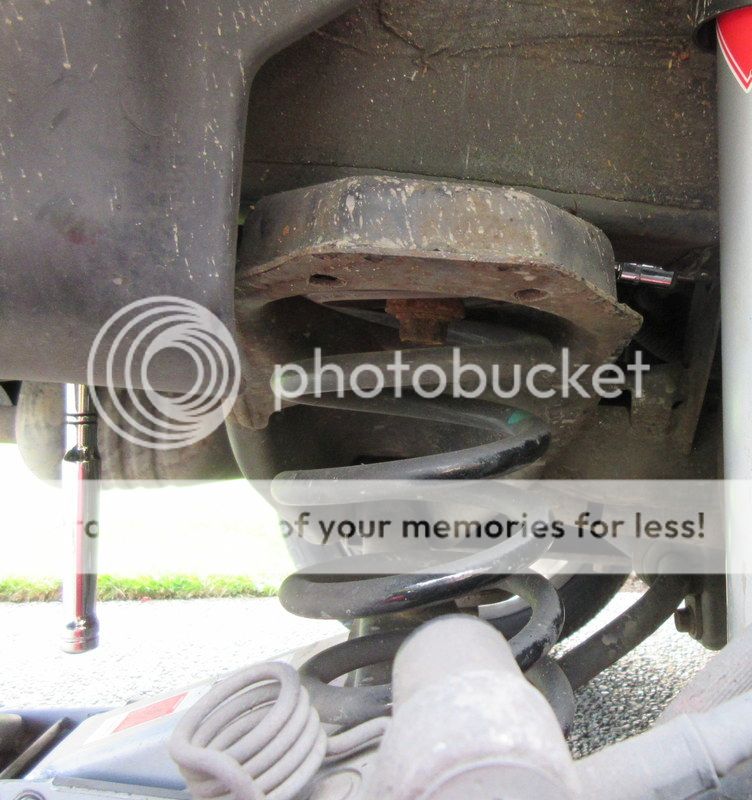
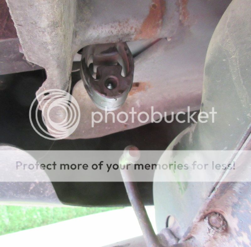
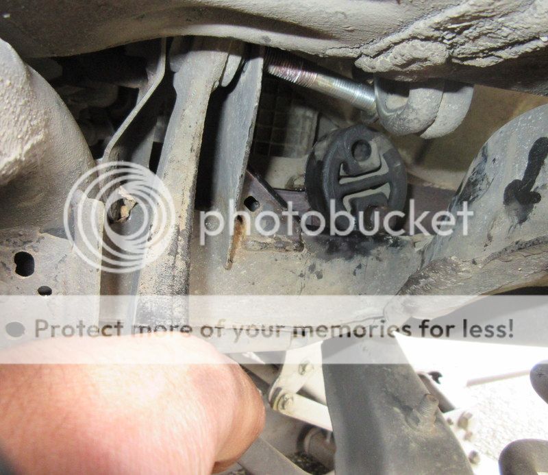
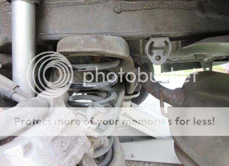
The third rear-most hanger is the one that blocks the inner bolt, and it's a bit tricky to remove. As before, use some soap and reach in from the wheel well with both hands. With the exhaust partially removed, you should be able to gain enough access with your left and right hands so that you can use your thumbs to push the rubber hanger off the pin. Since the rear of the exhaust is floating, you can push it towards the vehicle for extra leverage. The first pictures shows the hanger from the opposite side of the wheel well; you want to remove the hanger from the top pin.


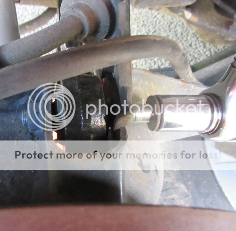
The hard part is done, and now removal of the inner bolt from the driver side is similar to the passenger side. Use a 12" extension to access the inner bolt from behind the rear crossmember.
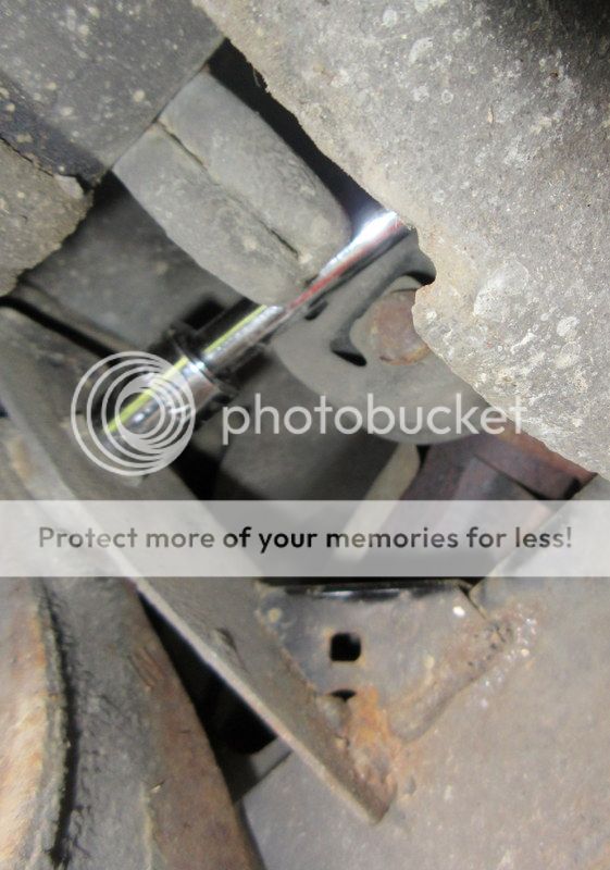
As I loosened the inner bolt, my socket eventually hit the hanger, so I had to switch over to a wrench to fully unthread the bolt.
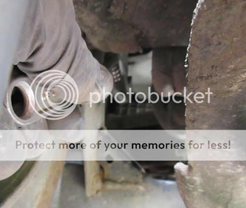
The hanger prevents the bolt from being removed straight back, but the bolt can be removed far enough to disengage the threads. Verify this by wiggling the bolt. With the outer bolt unthreaded, tilt the upper arm clockwise to angle the inner bolt down and slide it out and under the hanger.
Complete installation of the adjustable upper control arm as described for the passenger side. With the exhaust lowered, there is much better access to the inner bolt from behind the crossmember.
Once the upper control arm is installed, reattach the rubber hangers; this is much easier than removal since the hanger pins are bevelled.
Reinstall the wheel, lower the vehicle, and torque the lug nuts to 65 - 87 ft-lb.
Congratulations, you're done! If you set the length of your arms to match the factory arms, you should be pretty much close to the OEM camber, but it's worth having an alignment shop check your setup, or follow some of the tutorials on measuring camber yourself. After I do some more research, I'm going to adjust the arms to increase my camber (closer to 0 degrees) in an effort to reduce the tire wear on the inside edge.
Like many, I've had troubles with aggressive wear on the inside edges of my 2006 Mazda 5's rear tires, so I decided to install some adjustable camber rear upper arms. I purchased these arms from RockAuto: ULTRA-POWER MS40125

At $30 each, they're hard to beat and are a clone of the more common SPC arms.
The arms arrived with no instructions, but I found the instructions from SPC: http://www.spcalignment.com/instructions/67420-INS_WEB.pdf
I had trouble finding any more information that described how the adjustment nuts worked, so I decided to put together this picture tutorial to show how I made the initial adjustments on the arms according to SPC's instructions. I hope this helps someone!
The first thing I did was to take apart the arms to clean and lubricate the threads. After loosening the allen-head pinch bolt, I mounted the arm in a vise and turned the larger adjuster nut counter-clockwise. This took considerable force to break loose as this arm had some corrosion on the threads.


The adjuster nut is actually a hollow bolt into which the outer bushing is threaded along with a jam nut. These will come out as a unit.

I then placed the adjuster nut in the vise and turned smaller jam nut clockwise to remove the outer bushing. This is important: the jam nut and outer bushing are threaded left-handed, so clockwise to loosen and counter-clockwise to tighten.


Finally, I mounted the jam nut in the vise and with my hand, turned the outer bushing clockwise to remove it from the jam nut.


With all the pieces apart, I cleaned the threads and applied some anti-seize. Don't forget the pinch bolt. I'm hoping this will make future adjustment easier.


I then re-assembled the upper arm according to SPC's instructions by threading the adjuster bolt fully into the arm (clockwise), the jam nut fully onto the outer bushing (counter-clockwise), and the outer bushing fully into the adjuster bolt (counter-clockwise). At this point, the pinch bolt is still loose.

I don't have my OEM arms out yet to set the initial dimensions, but the best instructions I've found are to lay the new arm over the original arm and use the mounting bolts to align both bushings. To adjust the arm to the initial length, place it in a vise and turn the adjuster nut counter-clockwise while keeping the outer bushing from rotating. The combination of right-hand and left-hand threads will cause the adjuster bolt and outer bushing (along with jam nut) to simultaneously extend exposing an even amount of threads on each side of the adjuster nut.


When the initial length is set, tighten the pinch bolt to 20 ft-lb and run the jam nut tight against the adjuster nut. Again, remember that the jam nut turns counter-clockwise to tighten.

Once the arm is installed, it should be possible to adjust the camber without removing the entire arm by loosening the pinch bolt and jam nut, and turning the adjuster nut counter-clockwise to increase camber and clockwise to reduce camber.
One thing to keep in mind is that the length of exposed threads should be the same on the adjuster bolt and the outer bushing, and should not exceed 1/2" lest you end up with not enough thread engagement.
Anyways, I hope these pictures help. I'll let you know how the final install goes.
NOTE: The following procedures describe how I installed the adjustable upper control arms on my 2006 Mazda 5, and may not be accurate for your model vehicle. These procedures describe what worked for me and do not necessarily represent the correct or best way to perform the installation. Of particular note, the 2006 Mazda 5 workshop manual describes a different procedure that involves removing the lower control arm and spring. The torque values given come from the 2006 Mazda 5 workshop manual, but please double-check with your own resources.
Passenger-side Installation
I started with the rear passenger side as this is the easier of the two sides. Begin by loosening the wheel lug nuts and raising the vehicle. Place a jack stand in a location that will not load the suspension (you need to be able to move the suspension freely). I placed mine under the front control link bracket.

Remove the wheel and place it under the vehicle as an emergency backup to the jack stand; you'll be laying or reaching under the vehicle, so make sure it is safely supported.

Locate the outer bolt that holds the upper control arm to the hub and the inner bolt that holds the upper control arm to the frame.


Using a 17mm socket, break loose both the outer and inner bolts. Mine were pretty easy to loosen.


Note the brake line bracket, which is also held by the outer bolt. Remove the outer bolt; the hub will drop away from the control arm.


Remove the inner bolt by using a 12" extension to access it from behind the gas filler hose.


With both bolts removed, remove the upper control arm.

Here's the factory upper control arm beside the adjustable upper control arm.

Loosen the pinch bolt (counter-clockwise) and lock nut (clockwise) on the adjustable arm.

Using the inner bolt as a pin, align the fixed end of the adjustable arm with the factory arm. Adjust the length of the adjustable arm until the outer bolt can be used as a pin to align the other end of the arms. Increase length by turning the adjuster nut counter-clockwise while keeping the outer bushing from turning. The threads will evenly extend or retract on either side of the adjuster nut.


I set my arms to the original length since I plan to adjust them afterwards in-situ, but you could turn the adjuster nut 2 full turns (again, with the outer bushing held) to increase the camber. Anecdotal comments indicate that four 360 degree turns of the outer bushing from the factory length gets you in the ballpark of 0 degree camber. I halved this number since turning the adjuster nut extends the threads in both directions.
Once the length is set, tighten the pinch bolt (clockwise) to 20 ft-lbs and tighten the lock nut (counter-clockwise).


Note the grey (anti-seize) threads on either side of the adjuster and lock nuts. If the arm is properly adjusted, there should be an even length of threads on either side and these threads should not exceed 1/2". The threads beside the lock nut are critical; without them, the lock nut cannot be loosened to allow adjustment after the arm is installed.

Align the inner (non-adjustable) half of the arm with the frame bracket and loosely install the bolt (you want to keep the arm free to move).


Partially align the the outer half of the arm with the hub; the outer bushing will not fully-align until the suspension is raised.

Place a jack under the lower arm and raise the hub slightly to improve the vertical alignment of the outer bushing.

Push against the upper part of the rotor to move the hub into alignment with the upper arm bushing and then reinstall the bolt. Make sure to hand-tighten the bolt initially to prevent cross-threading and don't forget to install the brake line bracket.


Lower the jack to restore the suspension tension and then tighten the outer and inner bolts to between 66 and 90 ft-lbs.

Here's the passenger side adjustable upper control arm after installation. There's pretty good access to the adjuster nut from behind the wheel. To adjust, while facing the car, loosen the pinch bolt (counter-clockwise) and lock nut (clockwise). Turn the adjuster nut clockwise to decrease camber and counter-clockwise to increase camber. Retighten the pinch bolt (clockwise) and lock nut (counter-clockwise) after adjustment.


Reinstall the wheel, lower the vehicle, and torque the lug nuts to 65 - 87 ft-lb.
Post-installation note:
After setting the initial length of the arm, leave the lock nut loose so that there is some rotational play in the outer bushing. This will make it easier to realign with the hub. After the bolt is installed, tighten the lock nut.
Driver-side Installation
On the driver side, the inner bolt is blocked by an exhaust hanger. In my first attempt, I repeated the same steps as described for the passenger side. Once I had the inner bolt loosened, I spent 45 minutes trying to angle and push the bolt under the exhaust hanger. I eventually gave up and removed the exhaust from the three rear-most hangers; this gave me enough clearance to easily remove and reinstall the inner bolt. In retrospect, I should have begun by lowering the exhaust, so this is how I will describe the procedure, but because I did not do this initially, some of the pictures show the exhaust raised.
Follow the procedure described for the passenger side install until the point that you are ready to remove the inner bolt. Use some dish soap to lubricate the rear-most exhaust hanger pin (by the muffler) and slide off the rubber hanger. You should be able to do this by hand after sliding the rubber back and forth on the pin a few times to spread the soap.

Use the same technique to remove the exhaust from the second rear-most hanger; this is the one that you see facing you from the rear wheel well.

The third rear-most hanger is the one that blocks the inner bolt, and it's a bit tricky to remove. As before, use some soap and reach in from the wheel well with both hands. With the exhaust partially removed, you should be able to gain enough access with your left and right hands so that you can use your thumbs to push the rubber hanger off the pin. Since the rear of the exhaust is floating, you can push it towards the vehicle for extra leverage. The first pictures shows the hanger from the opposite side of the wheel well; you want to remove the hanger from the top pin.


The hard part is done, and now removal of the inner bolt from the driver side is similar to the passenger side. Use a 12" extension to access the inner bolt from behind the rear crossmember.


As I loosened the inner bolt, my socket eventually hit the hanger, so I had to switch over to a wrench to fully unthread the bolt.

The hanger prevents the bolt from being removed straight back, but the bolt can be removed far enough to disengage the threads. Verify this by wiggling the bolt. With the outer bolt unthreaded, tilt the upper arm clockwise to angle the inner bolt down and slide it out and under the hanger.

Complete installation of the adjustable upper control arm as described for the passenger side. With the exhaust lowered, there is much better access to the inner bolt from behind the crossmember.

Once the upper control arm is installed, reattach the rubber hangers; this is much easier than removal since the hanger pins are bevelled.
Reinstall the wheel, lower the vehicle, and torque the lug nuts to 65 - 87 ft-lb.
Congratulations, you're done! If you set the length of your arms to match the factory arms, you should be pretty much close to the OEM camber, but it's worth having an alignment shop check your setup, or follow some of the tutorials on measuring camber yourself. After I do some more research, I'm going to adjust the arms to increase my camber (closer to 0 degrees) in an effort to reduce the tire wear on the inside edge.
Last edited:
")
")

