LordWorm build commences...sort of

I didn't bother clicking on the links, but like I said, VICS is doing something, according to the flow bench AND dynos with it on vs off. But regardless, the stock intake manis are weak, and even with the VICS "saving the day" (sarcasm), it's still garbage.

thats my thinking. A correctly designed ram tunnel manifold will create upto 5 usable reflective waves through the rev range (the one i'm designing creates 4 - because to get the 5th one, the 1st reflection, I need runners that are way too long to fit). These reflective waves, especially the 1st, 2nd and 3rd waves cause a MASSIVE increase in air pressure at the valve. Enough that an NA motor with no other help (from ram scoops etc) can exceed 100% VE, and achieve air pressure at the valve in the order of 7psi....theoretically speaking, a correctly designed intake manifold should be able to break the stock FSDE :P

In short, such a manifold will make bigger gains, with more frequent "kicks" in the powerband compared to the stock heap of crap. Since when is "stock best", especially on our cars ;)
 
Last edited:
thats my thinking. A correctly designed ram tunnel manifold will create upto 5 reflective waves through the rev range (the one i'm designing creates 4 - because to get the 5th one, the 1st reflection, I need runners that are way too long to fit). These reflective waves, especially the 1st, 2nd and 3rd waves cause a MASSIVE increase in air pressure at the valve. Enough that an NA motor with no other help (from ram scoops etc) can exceed 100% VE, and achieve air pressure at the valve in the order of 7psi....

I've heard of this effect before, but never to the extent of 7psi. I've heard of great N/A tuners hitting 3-4psi, however I've never seen it with my own eyes.

theoretically speaking, a correctly designed intake manifold should be able to break the stock FSDE :P
Agreed. I started researching this back in Feb or March, and am actually still waiting on billet IM flanges from the machine shop (can you say expensive?).

In short, such a manifold will make bigger gains, with more frequent "kicks" in the powerband compared to the stock heap of crap. Since when is "stock best", especially on our cars ;)
A lot of our stock parts aren't bad, but yeah, the intake mani is the biggest weak link I can find. The only thing I'm not sure about is that if I do end up coming out with an IM (as planned), it will be costly to make (although the gains will be nice). I'm not sure how much interest there would be in it due to cost.
 
I've heard of this effect before, but never to the extent of 7psi. I've heard of great N/A tuners hitting 3-4psi, however I've never seen it with my own eyes.

Agreed. I started researching this back in Feb or March, and am actually still waiting on billet IM flanges from the machine shop (can you say expensive?).

A lot of our stock parts aren't bad, but yeah, the intake mani is the biggest weak link I can find. The only thing I'm not sure about is that if I do end up coming out with an IM (as planned), it will be costly to make (although the gains will be nice). I'm not sure how much interest there would be in it due to cost.

Mines going to be a one off. To do it properly the ram tunnel and plennum(the helmholtz part) NEEDS to be tuned to the motor. Its very dependent on VE, target RPM and so forth. On a turbo car, from what i can tell, the manifold is going to give gains through improved flow - because no matter how strong your pressure waves are from the tuned runners (which are the same regardless, and only the target RPM is a concern, because the speed of sound is whats used, not VE and so forth), pressure from the turbo is going to bury them.

Should be able to make a "max flow" beefy turbo intake manifold with very little effort or expense.

But an NA intake manifold, like most things NA, is going to need to be highly adaptable to different circumstances. An NA motor is a finely tuned beast - get something wrong and it wont achieve what you want it to achieve.

I'd be willing to share with you my 3D design for the manifold if it helps you bring something into production. Just got to find some time to get my manifold off and work out how much space i've got to work with.

4psi is easy - you can get that with a properly designed ram scoop (and a ghetto ram scoop will consistantly sit you at 2psi at high speed) - utilizing the reflections to boost the pressure is a whole different beast - you are unlikely to be able to see "7psi" on a boost gauge with it because the pressure build up occurs at the valve, and would be substantially weakened in the plennum where you are drawing your vac sources. The 7psi figure i've been quoted is apparently extrapolated from fueling requirements, not from an actual reading - but we shall wait and see. Also worthwhile noting that the 7psi figure is based on the 1st reflection, the single biggest kick you are going to get - and that means spastically long runners (the pressure wave which starts at a closed valve needs enough runner length to travel all the way back to the opening of the runner, and then back down in time to catch an open valve - 2nd reflection is much easier, half the runner length, the pressure wave bounces back twice, but you lose some of the strength).

I'm looking forward to being the first NA guy to bend a rod for reasons other than oil starvation or insane RPM. I'm also going to run a meth kit on it i think, for some saftey until the engine is built. Means i can't run it in my favorite "all motor" class because the rules define a power adder as anything device which boosts intake pressure, or adds any chemical to the fuel system after the fuel tank outlet. But at least I wont kill my motor before I can afford to rebuild it.....

I think there are plenty of weak links in the motor. Rods, stock exhaust manifold, stock intake manifold, stock intake system, stock head, lack of wall thickness in the cylinders limiting overbore (hence why i'm sleeving when i rebuild), poor rod ratio (not such a big deal for you turbo guys, but its a real pain in the butt for extreme NA buildups) - i could go on.. Needless to say, I intend to dress all of these issues in my build ;)

edit: you mind giving me your flow bench figures on the stock manifold? would be interesting to see what I can come up with on my custom job when its done - give me something to compare to.... also how does the stock intake manifold flow in relation to the stock head? is it a notable restriction or are they pretty well matched to one and other?
 
Last edited:
Should be able to make a "max flow" beefy turbo intake manifold with very little effort or expense.

Not quite. The flanges alone are killing me.

I'd be willing to share with you my 3D design for the manifold if it helps you bring something into production. Just got to find some time to get my manifold off and work out how much space i've got to work with.

Sure, it'd be cool to see what you come up with. Not sure what you're going for, but I'm trying to stay relatively close on the TB position. The hairy part is going to be EGR. Not sure if I could offer that or not.

The 7psi figure i've been quoted is apparently extrapolated from fueling requirements, not from an actual reading - but we shall wait and see. Also worthwhile noting that the 7psi figure is based on the 1st reflection, the single biggest kick you are going to get - and that means spastically long runners (the pressure wave which starts at a closed valve needs enough runner length to travel all the way back to the opening of the runner, and then back down in time to catch an open valve - 2nd reflection is much easier, half the runner length, the pressure wave bounces back twice, but you lose some of the strength).

So if you average it out, it's actually far weaker.

I'm looking forward to being the first NA guy to bend a rod for reasons other than oil starvation or insane RPM.

Haha, that's quite the goal.

I think there are plenty of weak links in the motor. Rods, stock exhaust manifold, stock intake manifold, stock intake system, stock head, lack of wall thickness in the cylinders limiting overbore (hence why i'm sleeving when i rebuild), poor rod ratio (not such a big deal for you turbo guys, but its a real pain in the butt for extreme NA buildups) - i could go on.. Needless to say, I intend to dress all of these issues in my build ;)

I agree for the most part, but from what i found, the IM is the weakest link. I also agree that our relatively small bore really screws us over, but that's more of a limitation than it is a "weak link" per say. I wish this motor was square.

edit: you mind giving me your flow bench figures on the stock manifold? would be interesting to see what I can come up with on my custom job when its done - give me something to compare to.... also how does the stock intake manifold flow in relation to the stock head? is it a notable restriction or are they pretty well matched to one and other?

Get with me on AIM.
 
Man... you guys are making my mouth water.... (bow) ...could I have a schematic, too? Don't think I'd ever be able to manufacture it, but hell, if it's possible, why not?
 
Not quite. The flanges alone are killing me.


Sure, it'd be cool to see what you come up with. Not sure what you're going for, but I'm trying to stay relatively close on the TB position. The hairy part is going to be EGR. Not sure if I could offer that or not.

Thats where i'm going to let you down - TB can't be in the same position (it'll be close, but visual inspection alone tells me its going to be quite the same spot). I'll also be running a smaller throttle body (don't laugh! helmholtz equations don't lie!). But i will be designing and fabbing the ram tunnel, new airbox (aussie regulations prevent you from having a bare naked pod filter in the engine bay, so i'm going to build an enclosure - also help keep heat out, and give me somewhere to mount the air temp sensor that won't impeed flow).

EGR is for babies :P i've deleted mine. No CEL. Aussie spec for the win! (i get no CEL for having the microtech either....) - So basically i could provide you with a pattern to build the thing from the manifold right through to the filter...i've gotta get the stocko manifold off first though. I get what you are saying though, a full intake replacement (which is what it amounts to) would have to retail up in the $2000 area - and i doubt theres a serious market out there for it, not in the NA area anyway)......thats why i don't intend on making more than 1....ever (so none of you guys get any funny ideas about making me weld you stuff!)


As for flanges - i'm just taking a drawing to a place that plasma cuts out of sheet steel (10mm), then having it decked to a suitable tollerence to give me a good seal on the head....would that be a cheaper option for you rather than fully machined billet flanges?

So if you average it out, it's actually far weaker.

Thats why i said "up to"... the actual pressure entering the cylinder is 7psi...but you wont read that in the plennum....at least thats my understanding of it. its worked out by extrapolating from fueling requirements to maintain AFR's when the kick occurs. Still, any positive pressure from an NA motor, without a ram scoop is nothing to be scoffed at! =) =)

Haha, that's quite the goal.

isn't it just? i only hope it lets go when the wife is driving it, so i can blame her, and tell her that now we have no choice but to build the race...er...i mean "street" engine ;)

I agree for the most part, but from what i found, the IM is the weakest link. I also agree that our relatively small bore really screws us over, but that's more of a limitation than it is a "weak link" per say. I wish this motor was square.

No doubt - manifolds are both heaps of crap. I'm not a fan of this "square engine" theory though....oversquare and undersquare engines do perform well....but its narrow bore plus long stroke plus physically short engine (stuff all spacing between the cylinders) that hurts us. We should have been given the FE3...and it should have been factory turboed...but mazda thought better of it :(


Get with me on AIM.

I don't have AIM.... you got MSN or something?
 
Man... you guys are making my mouth water.... (bow) ...could I have a schematic, too? Don't think I'd ever be able to manufacture it, but hell, if it's possible, why not?

Depends how attached i get to it. I'd offer it to someone like Kooldino first to help out a AV/AM - and to give the community the best possible chance at getting something half decent in the intake manifold department.....not sure if i'd want to let it go otherwise....i'll have a think about it....

I'll certainly want to get some "proof" that it works before the design gets leaked out there...otherwise i'd look like an asshat :P

so..in short, we'll see...no promises etc
 
Thats where i'm going to let you down - TB can't be in the same position (it'll be close, but visual inspection alone tells me its going to be quite the same spot).

How close? I'm trying to stay within an inch or so. I want folks to be able to use whatever piping and such they already are to their TB. If I can't do that, it will be much tougher to market.

I'll also be running a smaller throttle body (don't laugh! helmholtz equations don't lie!).

What source did you find all of the helmholtz info at?

But i will be designing and fabbing the ram tunnel, new airbox (aussie regulations prevent you from having a bare naked pod filter in the engine bay,

LOL.

EGR is for babies :P i've deleted mine. No CEL. Aussie spec for the win!

<--jealous.

My prototype will definitely not have EGR, and the jury is still out on whether or not the final product will.

(i get no CEL for having the microtech either....) - So basically i could provide you with a pattern to build the thing from the manifold right through to the filter...i've gotta get the stocko manifold off first though. I get what you are saying though, a full intake replacement (which is what it amounts to) would have to retail up in the $2000 area - and i doubt theres a serious market out there for it, not in the NA area anyway)......thats why i don't intend on making more than 1....ever (so none of you guys get any funny ideas about making me weld you stuff!)

Haha. Well, this would be for turbo app as well, so I wouldn't want piping and such with it, since everyone has something different.

As for flanges - i'm just taking a drawing to a place that plasma cuts out of sheet steel (10mm),

How clean is the plasma cutting?

I'm using billet aluminum flanges.

then having it decked to a suitable tollerence to give me a good seal on the head....would that be a cheaper option for you rather than fully machined billet flanges?

Beats me.

No doubt - manifolds are both heaps of crap. I'm not a fan of this "square engine" theory though....oversquare and undersquare engines do perform well....

Right, but an engine that's closer to being square (in regards to smaller motors at least) will generally have more advantages than an undersquare motor such as ours.

For instance...if our motors were more square, they'd be revvier for two reasons.

1-Shorter stroke = lower piston speeds at a given RPM = higher total RPM.

2-Shorter stroke (for a given displacement) = a larger bore. Larger bore = larger valves = better airflow through the head.

With my speedcircuit heads, we do everything we can to get more airflow through that head. The limiting factor at that point is the size of the bore. It's too small to allow for larger valves.

but its narrow bore plus long stroke plus physically short engine (stuff all spacing between the cylinders) that hurts us.

Yes, the spacing between the cylinders hurts us too. Or else we could do more about the small bore issue.

I don't have AIM.... you got MSN or something?

kooldino@hotmail.com
 
What source did you find all of the helmholtz info at?

All over the place... but the equation you want for working out the tunnel ram diameter (and consequently the size of the throttlebody) is

D = sqrt(CID * VE * RPM) / (V * 1130)


where CID is cubic inch displacement
VE is Volumetric Effeciency
V = velocity in ft/sec (this should not exceed 180 ft/sec according to my documents - so you plug 180ft/sec in at peak RPM)

thats for imperial measurements
for metric

D = sqrt(Liters * VE * RPM) / (V * 18.5)
 
Ok, made some progress tonight. Car is in pieces. Intake pipe work and IM are off, anything that got in my way was removed, both side mounts are off to get refilled/reconditioned (torn to all buggery...very bad...)

Rear mount is still being stubborn... The bolt thats a pain, we BELTED a socket that was 1 size too small down onto the nut, and turned it....and the nut just cheesed. Next step is to weld a stocket (yes, weld a socket) to the nut and try again. Theres not enough room in there to grind it out so this is the last throw of the dice, next step, remove sub frame and break out the oxi-torch...not looking forward to it if it comes to that.

Manifold has gone off to my 3d design friend to get measured up. Design on the new mani will commence shortly after.
jackstands are now the only thing keeping the engine in place... teehee.
 
Do yourself a favor and get those BOLT OUT kits. I've used them on that rear mount before. That tool is a direct gift from god.

Oh, and replace it with a high grade nut.
 
Do yourself a favor and get those BOLT OUT kits. I've used them on that rear mount before. That tool is a direct gift from god.

Oh, and replace it with a high grade nut.
elaborate?

one of the 3 mount nuts is butchered beyond recognition....
 
Make sure to get the ones with the square hole in the back, not the ones that you have to put a wrench on:

http://cgi.ebay.com/Craftsman-10pc-...ryZ42260QQssPageNameZWDVWQQrdZ1QQcmdZViewItem

Basically what you do is tap one of these sockets on. Now, the socket has reverse threads cut into it, so the more you turn it CCW, the farther the socket will bite onto the nut, which only continues to help you loosen the nut more.

You'll have that nut off in two minutes, tops.
 
Side mounts are on their way - few days at the manufacturer - gone for 95 duro poly to match the AWR front and rear.... should provide me with plenty of chipped teeth at idle!

As for Kooldino's magical sockets - i've found another brand (irwin tools) who stock them in Australia... And cool thing, theres a deal on at my favorite hardware shop... Buy any irwin tools MAPP Gas torch (the hottest brazing torch you can think of), and get a set of 5 of the Bolt Grip nut extractors... bargain at only $83! useful too, because a) if the nut extraction technique doesnt work i can go back to ye-olde burn the bastard off technique...and b) i need a brazing torch to build my merge collectors for the exhaust.

Tonights job is a bit of cleaning up and rattle chasing, as well as reinstalling the interior which has been out for a very long time.
 
Very cool. I've heard of Irwin, they seem like decent stuff.

You'll love them.
 
Another update - Well the bolt extractor didn't do the trick :( In the end there wasn't enough meat on the nut for it to grip on to and it just chewed the thing to pieces. Ended up grinding it off. No idea how, or indeed if, I will replace the 3rd mount stud. At this stage i'm content to suck it and see on 2 bolts. When torqued down, it is pretty damned solid, and theres plenty of other rides out there that only run 2 bolts on a rear mount - so maybe it'll be alright. I'll see how it goes once its all back together, and if it causes problems, i'll call out the mobile welding guys and get them to fix something up for me.

I've also been making some progress on the new intake manifold!

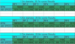
I've been playing around with the formula's, Trying to work out what the best balance between runner length, performance and airspeed is going to be. I'm trying to keep the airspeed at some sort of reasonable level because i'm concerned about airspeed impeeding flow. I need to find some formula's that equate velocity to flow in a given sized pipe to help me get a better target. Obviously once i've got a ball park on actual flow, i'll be able to see if a) the head is going to be able to flow that much air, and b) if the runner diameter i've selected will be able to flow that much air also. Both of these are critical factors - because if there is a bottleneck in the runners, or in the head, the whole thing won't work as intended.

I'm also having to make some compromises on the manifold design. Due to the length of the runners, I can't make them straight and thus I can't taper them. Idealy speaking, a 1% to 1.25% taper should exist along the length of the runner - I simply can't do this because of the path the runners are going to have to take. So to get around this, I will be using some rather aggressive velocity stacks in the plenum chamber to further assist in ramming the air into the runners. I need to find some formula's to see what effect these trumpets will have on the runner length - because in theory they should make the runners shorter (and it may simply be a case of getting the same overall runner volume as if the velocity stacks were not there). Any help would be appreciated :)

Another problem i've got is measuring the distance from the centre of the intake valves to the centre of the port they belong to. This distance makes up part of the runner (so with 20in runners, if the distance from port to valve is 3 inches, i only need 17in runners from the port to the opening of the velocity stack....). Kinda hoping Kooldino has a head off a car right now and can measure this for me ;)

anyway, attached are some runner calcs I've done. This first set of 3 calculations is done tuning the 2nd reflection to around 8000rpm to get a runner length, and then working out where all the other reflections occur. As you can see by these numbers, I will not being using reflection number 1 with these runner lengths. These numbers are tuned to my cams and i'm not 100% with these numbers yet so don't go using them because I can't be sure they will work! :P But it is interesting to see what effect runner size has on where the reflections occur, and what the airspeed (in ft/sec) is.

My next experiment with the math is to tune to the custom headers so the kick occurs at the same time that scavenging is due to occur in the headers. This will result in a bigger overall kick, but will probably also mean longer runners.
 

Attachments

  • runnercalc.webp
    runnercalc.webp
    26.5 KB · Views: 80
Other considerations

Just putting some things to consider in here:

Observations

1) the larger the pipe diameter, the shorter the runner needs to be - I believe this has more to do with the change in the overall volume of the pipe than the length of the pipe, but I'm not 100% sure of the relationship.

2) the higher the cam duration, the shorter the runner needs to be

3) the larger the diameter, the slower the velocity at the same RPM and volumetric efficiency.


Consider

1) What effect would a trumpet/velocity stack have on runner and ram tunnel length (given that it is effectively increasing the volume of the pipe) - In theory it should shorten it - but by how much?

2) What effect will pressure drop through the ram tunnel, plenum and runners have on the final pressure at the valve (the longer any of these are for a given diameter, the more the pressure drops. The larger the diameter for a given length, the more the pressure drops.). What effect will this have on the overall effectiveness of the manifold in generating positive pressure at the valve?

3) what is the maximum airspeed through a pipe of a given size before turbulent flow and restriction is introduced? What effect will air horn's/velocity stacks/trumpets have on the airspeed and will they work against me by exceeding the maximum flow of a given pipe (i.e. will i need to run larger pipe diameters if i use velocity stacks)

4) i'm of the belief that the resonance will occur more than once at and around each of the RPM points. Reason being that there will be a period of valve open time at both as it starts to open, and almost closes. What effect will this have? how wide will these "kicks" be - and should I alter the target RPM points to attempt to get a level of overlap between each pulse - what effect on the power curve will this have?
 
Last edited:
I can't answer any of your conundrums, but I have to say...

I can't wait for you to post up on headers... :D

Are the calculations for runner length after the throttle? Will you go MAP and individual throttle on this project? Since you're running Microtech, it's possible, and it might make custom runner design much much simpler (although it might take some work to fit 20 inches worth of runner under the hood and still put an air filter on them.

Headers are completely designed, no more conundrums on those, i even have the pipes bent, ready for cutting and welding..

The intake manifold - well... thats what i've got the conundrums on.... I already run MAP (microtech wont tune on MAF) runners are after the throttle. And after the plenum. It goes, Ram pipe, TB, Plenum, Runners.

I'm not going individual throttles. Reasons are 2 fold. Firstly, the car is driven (mostly) by my wife. She couldn't handle the obnoxious sound of individual throttles. Secondly, it would appear that a ram tunnel single throttle design will yield a far broader power curve, and in some cases, more peak power (if tuned correctly). I considered ITBs. I even have a set of throttles under the house ready to go (donated from a 4age 20 valve blacktop).

Another potential problem with quads/itb's is tuning. You can't tune on MAP because you can't get a consistant vac signal. So instead, you tune on throttle position, which isn't the best for street driving.

so for now, its going to be a single throttle, Helmholtz resonator, ram tunnel manifold.

And yeah, 20in of pipe is a heck of a lot to fit under the hood. One saving grace is that the runner length has to encorporate the distance from the port opening to the valve opening - so that may allow me to shave a few inches off the actual pipe i need to fit under there.
 
Back