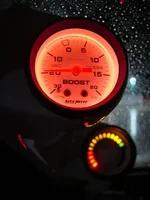
A/F gauge installation

PatMSP

Member
Hello guys,

I tried to install a A/F gauge in my new MSP yesterday. When I plugged the gauge to the pin #60 of the PCM (pink wire with blue stripe), I got no signal. This is very weird!!

So I decided to hook it up to the first O2 sensor. I need to know to which wire...the blue? the white?

Thanks a lot!
 
Last edited:
You probably tapped the wrong wire...I did the same thing. There's a pink wire with a dark blue stripe that's easily visible. The one you need is a pink wire with a light blue stripe, and it's covered under some gray shielding wire.
 
Did you make sure to hook up to a 12v power source when the key is on? Also, a good ground?
 
im curious why there is no signal from pin 60. More than one person has tried this and it hasn't worked.
 
A/F

Got_boost02 said:
whats the fifference in tapping into pin #60 over splicing right off the o2 sensor?

If you tap from the ECU vs. O2 Sensor you don't have to run another ******* wire in your engine bay to the Pillar.

The Wire is the only one with aluminum shielding on it. Be very carefull not to damage the integrity of it. It is what your ECU uses to control fuel delivery. :eek:

later
 

Attachments

  • interior night.webp
    interior night.webp
    16.5 KB · Views: 393
I did the installation with a friend who did it on his MSP and several others. He was really surprised too!
On top of that, I got a CEL today while cruising smoothly on the highway at 110 km/h. Unplugged the battery, it when off. Hope it won't come back!!

The wiring from pin #60 was really weird. It was splitted in 2 starting from the PCM. One of the wire from this split was hooked up to another wire from a nearby pin who was also splitted in 2. Really weird. :confused: When I put the voltmeter on the pink & blue wire, I only read 7 mV @ idle. It's supposed to read 250mV. The power supply to the gauge is OK cause now the A/F gauge indicates rich because it's not seeing any voltage difference (I got power cause there's light on the gauge).
 
When I hooked up my AF gauge to pin 60 of the PCM, I made sure I did a continuity check first. I unplugged my O2 sensor and attached one end of my Digital Multimeter to the pink blue wire at the connector, and the other end I back probed pin 60 on the PCM. I set my meter to make an audible beep when there is a short. Besides making an audible sound, the meter will show zero ohms.

If I remember correctly, there is more then one wire that is shielded. That may be why there is a wire running from pin to another on the PCM, the shields are common.

As far as trying to take a volt reading with your meter, since the signal is never really constant, your meter may not be quick enough to register a true reading in the dc volt mode. An O-scope would be the best piece of equipment to use to look at the signal.

One other thing, the three wires on the AF gauge, red is for Key On power, black is ground, purple is spliced into the Pink/blue wire. That's how you did it right? Just checking...:)
 
Last edited:
BremertonMSP said:
That's how you did it right? Just checking...:)
Of course! ;)

I know what I did wrong...As you just told, the wire is shielded, and I tried to connect my purple wire with a connector to the portion of the pink & blue wire that is shielded...(drunk)

I'll redo all the connections right. By the way, I think it would be better to solder these connections instead of using connectors since that the signal has a low voltage.

I'll keep you informed! :p
 
Everything's fixed!! The gauge is working fine! :)
So, rule of thumb : never put a connector on a shielded wire! ;)
 
Back