
You are using an out of date browser. It may not display this or other websites correctly.
You should upgrade or use an alternative browser.
You should upgrade or use an alternative browser.
The FrankenProtege Megasquirt Thread
- Thread starter xelderx
- Start date
Here is some info I have learned from MSnS build(fuel + timing) my 94 probe with an 03 mazda protege motor in it, blew the probe motor #1 rod blew threw block due to fuel in oil rod bearing was going, I didn't do all these things but it is on my mind to create these circuits and have them work the way I want. I have the probe and a 03 Black Mica MSP #0374, I might megasquirt my protege when I get all these issues figured out.
here is it:
My cranking pulse widths stock injectors:
12.5 for -40
3.9 for 180
interpolate the rest (linear curve)
ASE -40 100*
ASE 160 35*
*these will be different for different warm up enrichment values(see below)
The FS motor likes 12.0 - 12.5 AFR when below 55 deg. Using warm up enrichment up to an idle AFR of 13.5 - 14.5, use an already warmed up wideband and see what it is when it starts, use cold starts sitting for more than 4 hours...
Use fixed MAP(30-40Kpa) during ASE, this is essential as your MAP at cranking is close to 85-100Kpa and will be using ve tables from higher on the map bad idea for timing and fueling.
Your going to want to figure a way to control the alternator with the PWM signal to the alternator control circuit, refer to MSP ECU wiring diagram, or else you will be stuck with full load at 14.1 volts, the alternator will be taking hp away from your motor,also most cranking trouble begins with this (when the engine cranks the stock ECU doesn't put the alternator at full load until the engine is started(2 seconds pwm 0-X [X being pwm duty cycle to output the 13.2 volts] tapper time) , mazda has it so that the pcm sends a pwm signal to control the coils on the alternator, so in part it isn't charging full blast when it doesnt have to, i think this helps with gas milage also.
And when you turn your lights on, blower fan on, or bypass your ac routed safety switch in the ecu ( ecu compares a/c pressure so that it isn't running without r134a, you can bypass this and take the a/c input switch wire and wire it directly to the relay for the a/c clutch, please use at least 80 amp solid state relay to trigger A/C relay the voltage shock could damage sensitive components) in theory this should trigger the A/C fan and A/C compressor at once.
With this variance in idle you will either need to run an independent air bypass module, to let a small amount of air in when a/c is on... or you can tune closed loop idle (your adders are going to be a pain because of all the load fluctuation at idle, but it's possible to do, remember you can adjust your Idle Bypass Screw when tuning the PWM closed loop control, whatever way works best just remember modifying this screw will change cranking air entering the engine independently of the MS closed loop cranking idle-DC.
Also on the MSP ECU the fuel rail on hot restarts is allowed to cycle most of the fuel back to the tank, since on hot restarts the fuel will get close to boiling and no good for injection, this is accomplished by one of the vacuum solenoids attached to the FPR lasts for about 20 seconds after start I think its CLT temp > 175 the drop in static pressure should be minor as to not affect AFR too much. Minor code modification MSII (CLT temp>175, run time < 20 seconds).
Also you may want to still control the EGR valve with some kind of stepper motor controller at first i thought it was vacuum solenoid actuated I was thinking of my stock probe engine, the EGR in these cars is as follows
Lean Decel (I mean engine breaking) : Closed (0 duty cycle) Vac 20-38 (KPa 28-0)
Idle : Closed (0 duty cycle)
Full Throttle : Closed (0 duty cycle)
Mid Throttle : Open (5-60 duty cycle)
Low Throttle : Open (60-95 duty cycle)
The closer you are to full throttle(>99Kpa TPS>(DC 10 - max tps dc) the more closed the EGR gets, also it's closed underboost)
This would be a stepper motor circuit based off of the MAP output using an additional circuit on MSII.
So maybe Kpa 40-70 open, the rest closed.
or Kpa 40-90 for forced induction open, the rest closed.
This cools the combustion so it isn't to hot when you go to pound on the throttle this system is very important to preventing detonation in the FS engine, without it you EGT will skyrocket and not be good, possible predetonation/detonation.
In addition I would use knock sense module, or MSII knock detection circuit with the stock knock sensor and adjust it so that it just turns off, only monitor for knock at 1500<RPM<4500 because the valve train noise in these engines will cause it to go off above that... stock ecu takes this into account.
Also the coils used on the MSP, the nippon denso ignitor built in will need to be controlled with I believe spark output not inverted. I believe these (2)coils are similar to the ones on the mazdaspeed miata.You can still use the power transistors used on direct drive coils(Ford EDIS coilpack) with some minor modification.
I believe we have a 36-1 and a Nippondenso CAS sensor so dual wheel would be good to get accurate cranking RPM's, use the map sensor that way you dont have to worry about the crappy MAF getting clogged or going bad, the interpolation equations in megasquirt make a MAP work well for this engine, EAE (fuel wall wetting) in megasquirt I would take advantage of also and use TPSdot based accel enrichment.
Also make sure your cranking fuel pulse numbers are dead on, a back fire when cranking could cause your timing belt to skip teeth, break your starter, or crack your flywheel teeth, use conservative timing for cranking and you should be ok, 6-8 advance for cranking, GM cars have used as low as 5 advance on high compression motors.
Also I think the use of sequential injection (using the sequencer daughter card, router board) would work well on the MSP, more consistent fueling throughout the rev range.
Also on the MSP once you get the alternator to run correctly using a PWM signal to the very odd alternator we have, or install an alternator the doesn't use this method.. but since mazda designed this for ease of start and better fuel milage it may be worth it, I would get your battery voltage correction to a good value(lower your battery voltage and see how much AFR change, if they change too much adjust your correction factor, and also your injector opening time (use the alternation / sequential injection idle AFR change method see MS tuning guide). Use the temperature calibration tool(Easy Therm) and use the stock sensor except for intake air temp use GM sensor with pigtails, also I would move the intake air temp sensor to the high pressure side of the piping after the intercooler (weld a bung and use GM IAT sensor), that way MS gets a good value to make correction with(remember meagsquirts fueling equation), also you could retard timing based on intake temp and save your motor from unnecessary detonation.
Get rid of the ecu all together you'll be happier, use solid state relays for fan control like 80 amp for cooling fan(stock fan turn on at 201 i believe(use hyteries and have it turn off at 190) & a 100amp one for A/C clutch and a/c radiator Fan switching.
MSII extra custom Code addition, to add to the IDLE DC value when (power steering switch is activated - like when navigating a parking lot) for a set time and taper back down to original value, also to add an idle dc adder value for an A/C on input.
Also, the alternator uses a 400Hz pulse width, the duty cycle determines how much load the alternator can create, mazda did this to create a soft start so that electronic are gradually ramped up the 13.2 volts and also to lessen the load on the starter for easier engine cranking and starting. This control circuit would not be difficult to create.
Also would use VICS & VTCS control from 3 outputs from MS II, and open them based on RPM, as this increases low end torque.
#1 VICS solenoid Engine speed < 4,750 rpm: ON
#2 VICS (VICS solenoid valve) Vehicle speed >4,750 rpm: ON
and have the VTCS open as soon as after start enrichment are complete..
That is all I have right now.
Last edited:
Wow...lots of good information there. I don't need most of it since my setup is on a race car, but I will be taking a closer look at the CSE settings. I'm using an internally regulated alternator so no issues there. The A/C and EGR have been removed. I'll try and get my .msq file posted in the next day or so. I've been so busy with other projects that I haven't had a chance to update this thread.
Wow...lots of good information there. I don't need most of it since my setup is on a race car, but I will be taking a closer look at the CSE settings. I'm using an internally regulated alternator so no issues there. The A/C and EGR have been removed. I'll try and get my .msq file posted in the next day or so. I've been so busy with other projects that I haven't had a chance to update this thread.
Yes post your after start enrichment, and warm up enrichment bins, also state what injectors your using and your Req_fuel value, as the warm up bins look to the req_fuel to do the fueling increase percentage. Also how easily does your car start on a hot restart?? and when its cold.
Not running MS... but what temperature is it best to switch between the cold and warm maps? I'm noting running variances between cold running and hot running that I want to tune out with a coolant-temperature triggered air-fuel adjustment on my piggyback.
Also, when you say EGR is important to keep combustion cool... you mean EGR closed keeps combustion cool, right? If that EGR map is for the Protege, thanks... that'll help me quite a bit with my car...
Also, when you say EGR is important to keep combustion cool... you mean EGR closed keeps combustion cool, right? If that EGR map is for the Protege, thanks... that'll help me quite a bit with my car...
Yes post your after start enrichment, and warm up enrichment bins, also state what injectors your using and your Req_fuel value, as the warm up bins look to the req_fuel to do the fueling increase percentage. Also how easily does your car start on a hot restart?? and when its cold.
The car starts fine hot, but could use a little more adjustment to make it perfect. I'm running the car off a small motorcycle battery so it doesn't turn the motor over as quickly as a larger battery. I haven't had time to play with the cold start setting yet as I've been playing with the suspension and working on some other projects. I need to do that next week since the race battery is not strong enough to crank the car more than a few seconds before it gets too weak. It just started getting really cold around here so I'll try and remember to take my laptop over to the garage and do some tuning.
Not running MS... but what temperature is it best to switch between the cold and warm maps? I'm noting running variances between cold running and hot running that I want to tune out with a coolant-temperature triggered air-fuel adjustment on my piggyback.
Also, when you say EGR is important to keep combustion cool... you mean EGR closed keeps combustion cool, right? If that EGR map is for the Protege, thanks... that'll help me quite a bit with my car...
not exactly, your exhaust is cooler than your combustion temp... the EGR reduces pumping losses during low to mid throttle and allows the use of lean burn (better gas mileage), with the egr deleted make sure your AFR for mid to light throttle are not as lean as the car comes stock, you will have lean predetonation and maybe detonation when you punch the gas when you decide to floor it, from increased cyl temps, EGR reduces cyl temps when they are the highest(lean burn,cruise). Say your cruising along at say (40-50Kpa) (Idle is 28-35Kpa, Vacuum is less than 100Kpa, boost is over 100Kpa), Lean A/F ratio = higher EGT's, the EGR valve displaces oxygen containing air with inert gases(non-combustible) , when the EGR is not working the engine works harder to pump the air into the cylinders, the EGR gases act as a filler in the combustion chamber to lower EGT's during lean cruise(partial throttle), and to reduce pumping losses, for example say I want to pump 2.0L of air per second, but my throttle is only allowing for 1.8L air/sec, the other .2 isn't going to make it in and vacuum will be created in the cylinder making it harder for the engine to work, the EGR adds air proportional to the pumping losses programmed by Mazda, this maybe a common misconception but the egr does not make you loose horsepower, if its operating correctly it works with the engine to make efficient use of the fuel and allow for more Volumetric Efficiency at lower loads (past idle -> 3/4 throttle), the EGR isn't on at idle and its open most between partial and light throttle, it's not open at full throttle because there are no pumping losses (at least from the throttle body)... the EGR on the MSP is a 48 step bipolar stepper motor, a simple PIC controller with a MAP sensor(maybe even utilize the boost sensor for egr and use it as a map) could manage this EGR valve for low cost it would be a great addition the the megasquirt community for those who wish to maintain there EGR operation, fuel economy, and lower cyl temps for increased engine longevity and detonation prevention.
I hope this helps so everyone has a better understanding and can make an informed decision when deleting the egr...
In regards to your question I would say > 170F engine is warmed up, ideally 190-200 is fully warm.
< 150 still running on warm up enrichment maps at least on stock ecu's....
I think there is some tapering to do here as you don't want to go straight from a cold map to a hot map..
what controller do you have, and what options can you set for this?
--------------
Also, who thinks its stupid that the VTCS (intake runner flaps right before the intake valve) doesn't open until the engine temp is 150F, they should have it open when after start enrichment's are done, 2 minutes after start max it should be on.
Last edited:
The car starts fine hot, but could use a little more adjustment to make it perfect. I'm running the car off a small motorcycle battery so it doesn't turn the motor over as quickly as a larger battery. I haven't had time to play with the cold start setting yet as I've been playing with the suspension and working on some other projects. I need to do that next week since the race battery is not strong enough to crank the car more than a few seconds before it gets too weak. It just started getting really cold around here so I'll try and remember to take my laptop over to the garage and do some tuning.
Also, xelderx when you ms'ed your msp did you use the camshaft position sensor I am still confused about what signal the cam sensor puts out is it the notches that are 180 degrees apart, 1 notch on one side and 2 on the other(cam alignment markers)??, or does it read the holes in the center of the cam sprocket...? thanks.
I just used a 36-1 wheel on my megasquirted'ed probe-protege motor.. I'm thinking using dual wheel, for coil on plug and some kind of sequential injection where the injector fires before and during the intake valve opening event... and not randomly at any valve event like mega squirt currently does (2 alternating injections each at the firing of both coil outputs..), in theory this would allow complete spray of the injector in the open intake valve up to 2400 rpms.. any thing over that the injector would start injecting before the valve opened and end the injection when the valve is 3/4 open.. that way not it's not spraying on an overlap or after the intake valve closes and has to wait another 720 degrees to use the fuel.. i'm pretty sure this would give factory like starts also .. that's what i am excited about mostly...
Last edited:
Also, xelderx when you ms'ed your msp did you use the camshaft position sensor I am still confused about what signal the cam sensor puts out is it the notches that are 180 degrees apart, 1 notch on one side and 2 on the other(cam alignment markers)??, or does it read the holes in the center of the cam sprocket...? thanks.
I just used a 36-1 wheel on my megasquirted'ed probe-protege motor.. I'm thinking using dual wheel, for coil on plug and some kind of sequential injection where the injector fires before and during the intake valve opening event... and not randomly at any valve event like mega squirt currently does (2 alternating injections each at the firing of both coil outputs..), in theory this would allow complete spray of the injector in the open intake valve up to 2400 rpms.. any thing over that the injector would start injecting before the valve opened and end the injection when the valve is 3/4 open.. that way not it's not spraying on an overlap or after the intake valve closes and has to wait another 720 degrees to use the fuel.. i'm pretty sure this would give factory like starts also .. that's what i am excited about mostly...
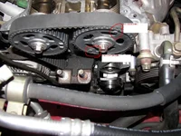
My MS is actually on just an N/A 2.0L. We aren't using the cam sensor. It's been a while since I took a good look at the stock cam gears, but they should have 3 notches. Here is a picture of an adjustable set and it looks like they have 3 triggers for the sensor.

not exactly, your exhaust is cooler than your combustion temp... the EGR reduces pumping losses during low to mid throttle and allows the use of lean burn (better gas mileage), with the egr deleted make sure your AFR for mid to light throttle are not as lean as the car comes stock, you will have lean predetonation and maybe detonation when you punch the gas when you decide to floor it, from increased cyl temps, EGR reduces cyl temps when they are the highest(lean burn,cruise). Say your cruising along at say (40-50Kpa) (Idle is 28-35Kpa, Vacuum is less than 100Kpa, boost is over 100Kpa), Lean A/F ratio = higher EGT's, the EGR valve displaces oxygen containing air with inert gases(non-combustible) , when the EGR is not working the engine works harder to pump the air into the cylinders, the EGR gases act as a filler in the combustion chamber to lower EGT's during lean cruise(partial throttle), and to reduce pumping losses, for example say I want to pump 2.0L of air per second, but my throttle is only allowing for 1.8L air/sec, the other .2 isn't going to make it in and vacuum will be created in the cylinder making it harder for the engine to work, the EGR adds air proportional to the pumping losses programmed by Mazda, this maybe a common misconception but the egr does not make you loose horsepower, if its operating correctly it works with the engine to make efficient use of the fuel and allow for more Volumetric Efficiency at lower loads (past idle -> 3/4 throttle), the EGR isn't on at idle and its open most between partial and light throttle, it's not open at full throttle because there are no pumping losses (at least from the throttle body)... the EGR on the MSP is a 48 step bipolar stepper motor, a simple PIC controller with a MAP sensor(maybe even utilize the boost sensor for egr and use it as a map) could manage this EGR valve for low cost it would be a great addition the the megasquirt community for those who wish to maintain there EGR operation, fuel economy, and lower cyl temps for increased engine longevity and detonation prevention.
I hope this helps so everyone has a better understanding and can make an informed decision when deleting the egr...
In regards to your question I would say > 170F engine is warmed up, ideally 190-200 is fully warm.
< 150 still running on warm up enrichment maps at least on stock ecu's....
I think there is some tapering to do here as you don't want to go straight from a cold map to a hot map..
what controller do you have, and what options can you set for this?
--------------
Also, who thinks its stupid that the VTCS (intake runner flaps right before the intake valve) doesn't open until the engine temp is 150F, they should have it open when after start enrichment's are done, 2 minutes after start max it should be on.
I have a Unichip Q. I can set for enrichment or leaning out via a fixed ratio based on coolant temperature (haven't bothered to touch that part of the programming yet) and I can trigger three separate maps based on a manual trigger or an automatic (sensor) trigger.
Can run things like a fifth injector or even the VICS with the accessory map... been having issues with EGRs... since emissiosn aren't a big issue here, we initially removed it, but the car ran hot at low rpms, so we had to put it back. Have been having trouble tuning around the adaptive part of the map, so we unplugged the O2 sensor to give us complete control... my only worry is whether this has an effect on EGR function. Currently having minor tuning issues, partially because the last time we tuned, we had a vacuum leak (which may or may not have affected EGR function) and because I'm running the car on propane. Vacuum issues affect the operation of the propane fuel system, and as the fuel vaporizer runs off of the stock vacuum system, the vaporizer needs retuning, too.
Set-up's way too complicated for my taste... have lines and hoses running everywhere... (boom03) ...just need to get this final re-tune out of the way.
Maybe if we leave EGR functionality as it is and run a map adaptation off of whether the EGR is open or closed? Is EGR merely vacuum based, or does the range of operation change depending on temperature? Because, after everything, that's what seems like is happening. If that's the case, we'll just tune with the EGR blocked, then run a map modification to adjust to EGR operation, so it doesn't run too rich.
----
I have the SR cams. Little machining, and they worked. Expensive, though.
New Posts and Comments

- Replies
- 2K
- Views
- 538K
- Replies
- 4
- Views
- 314
- Replies
- 8
- Views
- 924
New Threads and Articles
-
-
2013~2016 105 k - front suspension rebuild. How much you figure?
- By moonbandito
- Replies: 0
-