OK, gonna go for a lame attempt at a How-To. Most everything has been covered somewhere online, but maybe there's a few tidbits of new info here.
If I get any positive response from this one, I'll write one up for the fronts when I do them (still waiting on one strut to ship). If you think this one sucks, please say so and spare me the effort")
Tools Required
STEP 1 (Prepare Vehicle for the Job)
See STEP 1 picture.
STEP 2 - (Remove Upper Shock Mounts)
See STEP 2 picture.
STEP 3 (Disconnect Rear Sway Bar)
See STEP 3 picture.
STEP 4 (Remove Springs)
See STEP 4a through STEP 4d pictures.
STEP 5 (Remove Shocks)
See STEP 5a thru STEP 5c pictures.
WHOO-HOO! Everything's off!
STEP 6 (Remove Upper shock mount and adjust new shocks)
See STEP 6a thru STEP 6c pictures.
STEP 7 (Install new shocks)
Sorry, no more pics.
STEP 8 (Install new springs)
Sorry, no more pics.
STEP 9 (Reattach stabilizer bar)
STEP 9 (Finish up)
Well, that's it. I probably won't be able to embed the pictures in the right spots because only 5 attachments are allowed. Maybe a mod can fit it for me. Hope these instructions are helpful to someone.
If I get any positive response from this one, I'll write one up for the fronts when I do them (still waiting on one strut to ship). If you think this one sucks, please say so and spare me the effort
Tools Required
- (2) Jackstands
- Hydraulic Jack
- Vehicle's tire jack
- 13MM and 14MM box-end wrench
- 12MM, 13MM and 17MM socket
- 5MM allen wrench
- Crescent wrench or locking pliers
- torque wrench (socket type)
- torque wrench (dial type) (not essential unless you're anal)
- hammer
- pry bar
- cheater bar (unless you have super-human strength or an impact wrench)
- socket extension (probably not essential, but helpful for using torque wrench)
STEP 1 (Prepare Vehicle for the Job)
- Break the lugnuts loose on the rear wheels.
- Jack up the rear of the car and set it on jackstands. You might want to block a front wheel, although if you use the hydraulic jack the way I did, the car moves backward when you jack it up anyway. Get it up as high as you can - it will make the job a little easier.
- Remove rear wheels.
See STEP 1 picture.
STEP 2 - (Remove Upper Shock Mounts)
- Using a 12mm socket and extension, remove the two upper shock mount nuts.
See STEP 2 picture.
STEP 3 (Disconnect Rear Sway Bar)
- Break the top endlink nuts loose using a 13mm socket wrench.
- Using a 13mm box end wrench and 5mm allen wrench (to keep bolt from turning), remove both top nuts.
- Swing the sway bar down away from the control arms.
See STEP 3 picture.
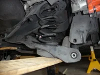
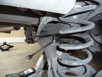
STEP 4 (Remove Springs)
- Break the control arm outer bolt loose using a 17MM socket and a cheater bar. This baby's on tight!
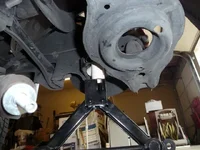
- Place the tire jack under the control arm to prevent the spring from flying out when the bolt is removed.
- Remove the bolt (lots of threads - will take a while).
- Lower the jack a little bit - the control arm will probably stick in the mount, so use a hammer to loosen it so it'll drop. Just keep hammering it while you lower the jack.
- Once the spring is no longer under compression, remove the jack and push the control arm all the way down.
- Remove the spring.
- Remove the upper spring seat rubber from the old spring and put it on the new spring.
- Repeat for other side.
See STEP 4a through STEP 4d pictures.
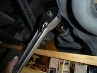
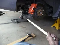
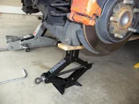
STEP 5 (Remove Shocks)
- Break the lower shock mounting bolt loose using a 17MM socket and a cheater bar. This one's a little harder to get leverage on, so prepare to do a little cussing. And you thought the control arm bolt was on tight...
- Once the bolt is sufficiently loose, at a minimum I would recommend sticking the jack under the shock to keep it from extending through the mounting hole once the bolt is removed. I didn't do this, and was having a lot of trouble getting the shock out, so let me tell you a little trick I used to make it easier....
- Stick a piece of PVC pipe about 3" long in between the jack and the bottom of the shock. You could also use a block of wood or any other material that is about 3" long and small enough to fit through the mounting plate.
- Remove the bolt completely and jack that puppy up until the bottom of the shock clears the mounting bracket (you young guys without back trouble can probably just stick the jack under the shock and leave it at that, but it was not easy for me to get that shock out without a little help).
- Either lift the shock by hand or knock it off the support, sliding it towards the front of the vehicle. Let it extend and remove it.
- Repeat for the other side.
See STEP 5a thru STEP 5c pictures.
WHOO-HOO! Everything's off!
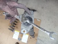
STEP 6 (Remove Upper shock mount and adjust new shocks)
- Using a crescent wrench or locking pliers to keep the shock shaft from turning, use a 13mm box-end wrench to remove the upper shock mounting bolt. Unless you have a dial-type torque wrench, you might want to remember how hard it was to get off, so you can retorque appropriately when you do the new one (obviously, a socket type torque wrench is of no help with this particular nut).
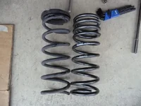
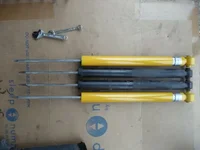
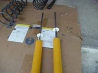
- See STEP 6a picture for a comparison of the OEM shocks and the Konis.
- It's time to adjust the Konis. Your initial setting is most easily done off the vehicle. It's easiest if you have a vise, but you can also do what I did. Use a crescent wrench (or locking pliers) on the shaft end. Place the wrench on the ground (with the wrench attached to the shaft) and step on it to keep it from turning. Compress the shock all the way, then rotate until you feel the shock go down a little further (maybe 1/8 inch). This means the adjustment mechanism is engaged. Now while holding the shock fully compressed, rotate the shock fully clockwise (CLOCKWISE=FIRMER, COUNTER-CLOCKWISE=SOFTER). You will feel a little click when you get near the adjustment limit, then soon after you will encounter resistance. Do NOT try to force it more. The shock does not click at intervals - it only has a little click at each end of travel. Now release the shock without turning it just to see if it rebounds very slowly (if you did it right, it should).
- Recompress the shock (you should still be able to engage the mechanism if you didn't twist the shock) and rotate the shock clockwise until you reach your desired setting. The total adjustment range is about 2.5 turns, so I set mine to a little over one turn from fully stiff.
- Release the shock to disengage the mechanism.
- Repeat for the other shock. The shock do NOT behave identically, so once you have a rebound rate that you like for the first shock, adjust the other to MATCH it. Compress both shocks and let them fully extend simultaneously, and keep adjusting one or the other until they both extend at the same rate.
- Once they are adjusted, slide the white ring over the shaft and put the top mount back on. Using the Koni-supplied nuts ], tighten the first nut to 37 ft-lb (or good 'n tight if you don't have the dial0type torque wrench), then add the jam nut and tighten it as well.
See STEP 6a thru STEP 6c pictures.
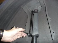
STEP 7 (Install new shocks)
- Coming up from the inside front of the vehicle, get the upper shock mount into the studs.
- Compress the shock until you can get the lower end into the mounting bracket (have your lower bolt handy). Reattach the bolt and tighten everything up. The top nuts are 16-21 ft-lb, and the bottom bolt is 55-75 ft-lb (good luck - try not to dislocate your shoulder here). NOTE: It is recommended to actually torque the lower shock bolt to spec when the vehicle is on the ground (this is what I did). It's a little harder, but if you want to do so, get it mostly tight and then wait until the vehicle is lowered. JUST DONT FORGET TO DO IT!
- Repeat for the other shock.
Sorry, no more pics.
STEP 8 (Install new springs)
- Insert the new spring with attached spring seat into place, making sure that the top is centered properly, and that the end of the spring on the bottom end is seated into the large hole in the control arm.
- Jack the control arm back into place, making sure the spring remains properly seated. You'll probably need a pry bar and hammer to get the control arm holes to line up with the mounting bracket.
- Torque the control arm bolt to 55-75 ft-lb.
- Repeat for opposite side.
Sorry, no more pics.
STEP 9 (Reattach stabilizer bar)
- Rotate the stabilizer bar back into place and reattach the upper endlink nuts. The torque spec for these is 30-40 ft-lbs if you have a torque wrench that works in this case.
STEP 9 (Finish up)
- Throw the wheels back on and lower the vehicle.
- Torque the wheel lugs to 75-85 ft-lbs in a star pattern (to prevent rotors from warping).
- If you didn't torque the lower shock bolts before, do them now (55-75 ft-lb)!
Well, that's it. I probably won't be able to embed the pictures in the right spots because only 5 attachments are allowed. Maybe a mod can fit it for me. Hope these instructions are helpful to someone.
Attachments

Last edited: