How To: DIY Ground Wire Kit

If you dont want to lose the thread ,bookmark it in your favorites ,thats what I do when I want to vist a thread on a regular basis .
 
How come 6A doesn't connect to 6B? It connects to the power steering reservoir bolt, and not where 6B is that.
 
Uh, 6A does connect to 6B. The picture with the green markup is just showing you where the Power Steering reservoir bolt is for some reason. If you look at the circled 6B, you can see it is a bolt with a ground wire connected. That's the place to mount the wire 6.

You can see my groundwire pics here:
http://www3.sympatico.ca/robin.smith1/Battery-Ground.jpg
http://www3.sympatico.ca/robin.smith1/Engine.jpg
http://www3.sympatico.ca/robin.smith1/RightSide.jpg
The Right Side shot shows where the red wire (called 6A - 6B in the other pic) goes.
 
I got the wires and 24K gold plated terminals today and I made the wires. Plan to install them on the car over the weekend. I'll take some more pics when done.

Here are all the wires and a close up of the wires and 2 of the connectors. They are crimped, shrink wrapped and then have the rubber covers over the connectors.
 

Attachments

  • Wires.webp
    Wires.webp
    165.4 KB · Views: 379
  • Connectors.webp
    Connectors.webp
    242.6 KB · Views: 342
Last edited:
I've read this whole thread, many times actually, but I have yet to find out how to crimp the terminals to the wires or the battery? Sorry if this is a stupid question but I have never done this before and would like to do it right. Ane another question how do you wire everything if you have an amp kit already connected to the battery terminal?
 
i just used one of those huge clampers that is attached to a table, and a hammer. My crimpings aint going no where. But doesnt it seem weird the the screw at the front of the engine block is grounded to 2 places or am i wrong?
 
as long as you are cutting of the right amount of the wire sheath (about 1/4 inch - depending on your terminals) all you do is insert them and using a crimping tool, crimp that bad boy down.

re: amp kit.. couldn't youjust undo the amp kit and attach that? i'm thinkin you probably wouldn't have to though seeing as you want to connect to the ground (neg) which your amp kit won't be attached to.

in the pic the amp kit is wired to the left side.
the right battery terminal is where the original ground is attached.

second pic is closeup of ground terminal.

re: the 2 points from the front. i believe the whole point is to provide grounding points. 1 going to the body (shorter) 1 going to the battery terminal ground. (longer) i'm no expert but it would seem that these are two quality grounding points. sure you could do just one. but you could also do two.. lol... (yeah like that schpiel was a BIG help.. lol)
 

Attachments

  • IMG_2407 (Medium).webp
    IMG_2407 (Medium).webp
    51.5 KB · Views: 486
  • IMG_2409 (Medium).webp
    IMG_2409 (Medium).webp
    59.7 KB · Views: 685
Question About DIY "Hyper Ground Wire Kit"?

Gro Harlem said:
I just made and installed my own "Hyper Ground Wire kit"!! It cost me $48 shipped for the wire and terminals and about 1.5 hours to make and install the wires.

Here is the How-to write up:

http://www.protegenetwork.org/pro/1stgen/articles/howto/groundwire/

What do you think?
What is the Purpose of a Grounding Wire for?? I have read some of the threads and I don't understand how a grounding wire can increase HP or Tourque, please help and submit any web links for kits already made:)
Big Dog
 
the link on the original post no longer works!!! Could someone tell me the grounding points?
 
<BOV>
Bloody hell, does no-one read a thread through before posting?

There are so many posts in this thread saying, the original link doesn't work, yet all the info you need is in this very thread as everybody so helpfully added all the info from the original link and more throughout.

I suggest you read all the posts.
</BOV>
 
benzero said:
i bought that kit. no instructions. how the hell does the whole circle earth thing work? i was just going to run it like everyone else. anyone have any instructions on where that circle thing goes?

Same question here. How to install this? Where does that circle thing do? Can anyone help us out?
 
lazyme said:
Same question here. How to install this? Where does that circle thing do? Can anyone help us out?
from my undestanding (so take this with a grain of salt) it works like this

your car is one big ground..
every electrical device in your car is grounded to the chassis (i.e: ecu and all sensors for the ecu[keep that thought in ur head)....
if you connect all the grounding points you will have better grounds and i have been told your sensors will get better more accurate readings and less electrical "noise" through the system.

when i did this used monster cable 4 gauge grounding wire, connectors from auto zone (i'll explain how the wires are connected to the connectors i.e: crimped in a second) and a terminal from auto zone.

connections: i dropped a ball of solder (i dont think i spelt that right) in the connector, slid the wire in the connector, then heated up the connected so the solder melted to the wire/connector, then i put the connector in a bench vice and made a VERY good crimp onto the wire, i did this to all but one of my wires and that one has come out recently and was dangerously close to being in my belts (eep) i cna only imagine what a 4 gauge wire would do to a rubber belt.
 
Hey guys i just wanted to know what are the best points to attache the ground wirres to ?

And where you guys saw the most gains ?


Thanks alot !
 
The grounding points should be mentioned in this thread.

After doing this mod I saw no gains whatsoever, this didn't even cure the dimming headlights. The only thing I noticed was smoother idle.
 
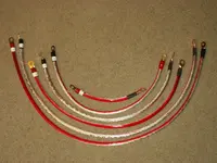
I just picked up some 8 awg ground wire from KnuKonceptz for this ($0.37 per foot for 8 awg, $0.49 for 4 awg). I am also using Monster 200 series ring terminals with sealed ends to eliminate any corrosion inside the wiring ($3.50 per pair from local electronics store and I bought 8 pairs). I will be using the KnuKonceptz positive battery terminal (which I already had for my amp/sub) and a negative battery terminal from Stinger ($11.50 with shipping bought on ebay). The surprising thing was that the Monster ring terminals were more expensive than all the wiring and the neg. battery terminal combined. It's because they are "Monster" but it was all I could find that were sealed off.

As recommended earlier, I will be soldering the ring terminals onto the wire to eliminate any chance of wires coming loose. Also, every ring terminal to wire connection will be protected further with heat shrink tubing. Basically I'm trying to reproduce 1sty's famous kit (except I opted for 8 awg wire while his was 4 awg).

What do you guys think of me doing another full write-up when I do mine? It's a pretty straight forward thing to do, but supplying info like lengths of each wire and specific contact points might come in handy for the DIY-ers.
 
Last edited:
I just installed a DIY ground wire kit and now my check engine light is on. Has this happened to anyone else? Its error code P0031 - there is low voltage to the front O2 sensor.
 
has any one in ft. lauderdale done this? i can't seem to find any one who sells 4ga wire by the foot
 

New Threads and Articles

Back