Berty's Cosmo

So what triggers the solonoid to open the 84 degree thermostat? I still dont understand what the point to the one lower is?

I was told that the higher temp on a Cosmo was beneficial to long term engine wear characteristics, although I dont doubt that it could well have been about emissions.

Also, I dont have a parts book nearby, but Im pretty sure that the Mazda genuine parts are the exact same number! I'ver never seen anything berfore this that has diferenetiated them, by heat range. What was your source on this?

Kramer

There was a recent thread on RX7 club about this...

http://www.rx7club.com/20b-forum-95/20b-dual-thermostat-1001493/

There is a post further down with a picture from the service manual (albeit in Japanese). If I understand it correctly, the rear is the 82 degree thermostat which is held normally closed by a solenoid. Under certain conditions, namely engine load the rear, 82 degree thermostat opens to aid in cooling.

I was also talking to Drew about this and he said that the higher running temp aided in burning the copious amounts of fuel that the 20B factory management uses.

I have seen pictures of factory thermostats with the temp actually stamped onto them.
 
Looking awesome Berty and great work. Love the RE:A kit, I would love one as would another Cosmo owner in the UK. You'd never have issues selling it!

Rgds

Ant

Kit looks really good.
As RE-A are not making these anymore, i'm sure you could do pretty well by getting some moulds made up. I'd put my name down for one for sure.

Nice work on the pro ratchet. Mine is booked in for a swap to a manual S5 Rx7 T2 box. Will post up some pics once its done.
 
Last edited:
Nice work on the install!!!!

Thanks mate :)

Kit looks really good.
As RE-A are not making these anymore, i'm sure you could do pretty well by getting some moulds made up. I'd put my name down for one for sure.

Nice work on the pro ratchet. Mine is booked in for a swap to a manual S5 Rx7 T2 box. Will post up some pics once its done.

I would love to make some molds but unfortunately I don't have the skill to do that. I would really like to do it for my own sake though.

I am selling my manual set-up if you are interested. I have decided to build up the auto box after thinking about what Rodneoo has said. Unfortunately this means more $$$ than what I had budgeted for.
 
More pics of the Pro-Ratchet install. Ignore the blurry phone pics.

This is the bracket from above before shaving more material off.

IMAG0298.jpg


... and this is what it looked like once I took the angle grinder to it and removed some of the extra metal as well as shaved the bolts down to their minimum size.

IMAG0302.jpg


The bolts on the side of the adapter were a bit problematic because they were too big and would have prevented the adapter from making a good seal on the trans tunnel. For this reason, I have to use some bolts with a slim head profile so that it could still be bolted down correctly.

IMAG0308.jpg


The next challenge will be making this fit

IMAG0304.jpg


Looks like it will only work if it is sideways

IMAG0305.jpg


IMAG0306.jpg


Oh well.

On a different topic, the new valve body has arrived. After chatting with a local transmission shop I have opted to rebuild and strengthen the box. On top of the manual valve body will be a set of billet intermediate servos and Kevlar bands. Extra clutch packs will also be added in during the build. I won't be doing this myself though. The auto gearbox is a frightening beast.
 
Just a small update with a few technical notes;

Microtech LT12:

My Davies Craig digital fan controller decided to die last Tuesday so I decided to install another relay and run the thermo fans from the Microtech's Aux output. The factory wiring diagram only lists one output for this ECU, a negative switching ground wire. I promptly tracked this wire down in my harness and used it to trigger the relay but with no luck.

Turns out that my LT12 was sent from the factory with three Aux outputs. Two of which seem to be a negative switch for relays and the other I presume is a PWM output based on what the multimeter was reading.

This might be common knowledge but I couldn't find much on the net about this (nor Microtech's website) so I thought that I would share. If you have a LT12, and you have the following EXTRA wires in your then there is a good chance you have extra outputs;

White / Black
White / Red

One of the wires is seventh from the left on the bottom row, the other seems to come out of the plug which goes to igniters.

If you have these extra wires then these are more than likely extra Aux outputs. I found that the white wire on mine (which is usually the aux output) was actually some type of PWM output.

:)
 
Last edited:
Achievement unlocked.

hahaha how did that happen? A fault somehwere?

I wish it was legit but alas no...

I had the famous dash black-out problem which pretty much everyone seems to go through and this is what happens when the dash comes good.

Seems to be a grounding issue under the dash as the engine block grounds are good.

I haven't bothered to reset it because I like freaking out passengers.
 
Last edited:
I've been out of action for a while after being in a car accident in January. Some idiot ran through a red light and into the side of my car - luckily I was in an SUV and it took the impact pretty well. I ended up getting off with a broken rib and a displaced rib so I haven't been able to do much on the car since.

I have been feeling better recently so it is time to get started installing this...

IMAG0330.jpg


Although I am going to leave the pro's to do the gearbox internals, I will do the other parts like the shifter and cooler install.

This is an part update and part how to! :)

I ended up getting a Davies Craig trans-cooler - the biggest one that they have which is designed for engines above 4L.

To take the front of the Cosmo, you will need to remove the headlights and grill. Once you have access to the bumper bolts, there will be four 14mm bolts in the center, three 10mm either side connecting to the front quarters and one 10mm per side connecting the lower lip the underside of the quarter panel. The only thing that you will need to remove are the plastic clips which hold the front under-trays on.

This is a trial fitting of the new cooler...

IMAG0347.jpg


The new cooler is much thinner (about 1/3 thinner) than the original, but the frontal surface area is much greater. Removal of the old cooler is pretty easy - just a bunch of 10mm bolts to remove.

Now, if you are still running the factory radiator, then your trans cooler lines will run to a heat exchanger underneath the radiator. You can still retain this system, however I would recommend bypassing just to remove any additional load on the Cosmo's marginal cooling system.

If you want to buy new hose, you will need about three meters of 3/8 line. (although 2m is fine 3m will give you a bit of leniency in terms of mounting the new cooler).

This is what it looked like after installing...

IMAG0349.jpg


The issue with this is that you have massive gaps for the air to escape with. Air will take the path of least resistance so a new shroud needs to be made.

IMAG0350.jpg


I just bought some 0.75mm galvanized steel to do the job. Lucky for me, my wife bought me an air compressor for our anniversary. I went out and bought an air nibbler to do the cutting.

IMAG0350.jpg


Here is the first part of making the shroud. Lots of trial and error (because I didn't have any cardboard left over to make templates!)

IMAG0354.jpg


Here is the finished (ugly but functional) finished product.

IMAG0355.jpg


In the end it took about three hours. Here is a quick list of tools and parts;

Sheet of metal - 0.75mm steel or 1.0mm aluminum
Davies Craig Trans Cooler (comes with some 3/8 hose and clamps)
1m of 3/8 hose (fuel or trans hose is fine)
L brackets
various rivets & bolts.

Tools;
Air Nibbler
Die Grinder
Drill
Drill Press
Rivet Gun
Sockets
Spanners
 
Last edited:
Hi Berty,, I thought you had been a bit quiet recently,, glad to hear you are OK after the accident and even more so that you were not driving the cosmo at the time
trans cooler looks good,, did you sell the manual gearbox kit yet?

Frank
 
Hi Berty,, I thought you had been a bit quiet recently,, glad to hear you are OK after the accident and even more so that you were not driving the cosmo at the time
trans cooler looks good,, did you sell the manual gearbox kit yet?

Frank

Hey Frank, yep getting back to normal now which is good. I also picked up my car from the panel shop on the weekend. Took them nearly 7 weeks to get all of the parts and fix it. It's good to have the Cosmo support vehicle back in operation (rockon) I did sell the gearbox a while ago - in fact I was taking the gearbox to the courier when I was hit by the other car!

I did some more work on the weekend. I was originally going to put the pro-ratchet into the car however when I jacked the car up, I found that the last place to work on the exhaust had removed some of the flanges which meant that to get to the gearbox, I would of had to remove the entire exhaust from the dump back. As I was doing this without any help (and because I am recovering from broken ribs). I decided to do something different. MORE TURBO!

I've had a bigger turbo sitting around for a while now... I posted a picture of it a few pages back when I initially bought it. Here you can see the new turbo (left) beside the old turbo. The inducer is 12mm wider in diameter so about 25-30% bigger front wheel.

IMAG0359_Cropped.jpg


Some of you also might remember when I narrowly avoided an engine bay fire after my oil return line melted. When I fixed up that issue, I thought that I had resolved the problem by altering the alignment of the return and wrapping it in heat wrap. Turns out that I was setting myself up for disaster again. This is what the return line looked like after only a few hundred km's of travel. Scary stuff!

IMAG0363.jpg


I made up a new oil return line (again). This time, I have a -10 fitting on the bottom of the CHRA. That fitting then goes to a 35 degree male to male, -10 bend. This now completely guides the turbo return forward and away from the manifold. I had some concerns that the angle would affect the drainage rate, but it seems to be okay so far. I still haven't driven the car yet, just let it idle.

Here is the end result!

IMAG0362.jpg


Here are a few technical notes;

-I used a set of banjo bolts for the water feed to give better clearance. These fittings have -6 ends on them.
-Water feed for the CHRA now comes from the front of the thermostat housing where the L shaped elbow is. I believe that this was the water feed for the old turbo's anyway. This uses a 3/8 fuel hose into a -6 90 degree bend. From there, a -6 adapter connects to the braided hose.
-Water return goes into the top radiator hose. I removed the forward temp sensor (used for the auto trans) and put an M15(or M16) to -6 fitting.
-The turbo uses a weird oil fitting for the inlet. It is 7/16 -24 thread instead of the 1/8 NPT on the old turbo. Here I am running a Speedflow 7/16 to -4 adapter. The top of the oil feed is using a 1mm Speedflow restrictor. I am yet to check the oil pressure here.
-I couldn't use the water fitting at the bottom of the water pump because the manifold now fouls this.
 
Last edited:
Looking great Berty - can't wait to hear your feedback after you put her through her paces (cheers2)
 
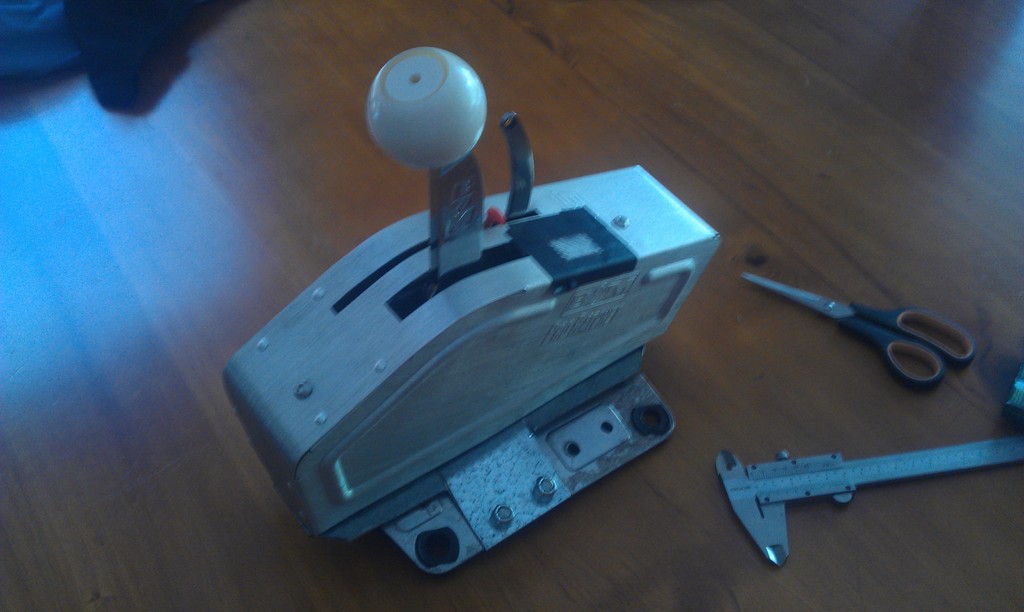
Installation of the B&M Pro Ratchet happenned during the week. A huge thanks to rodneooo for his help in answering questions.

Here the heavy lifting begins...

IMAG0392.jpg


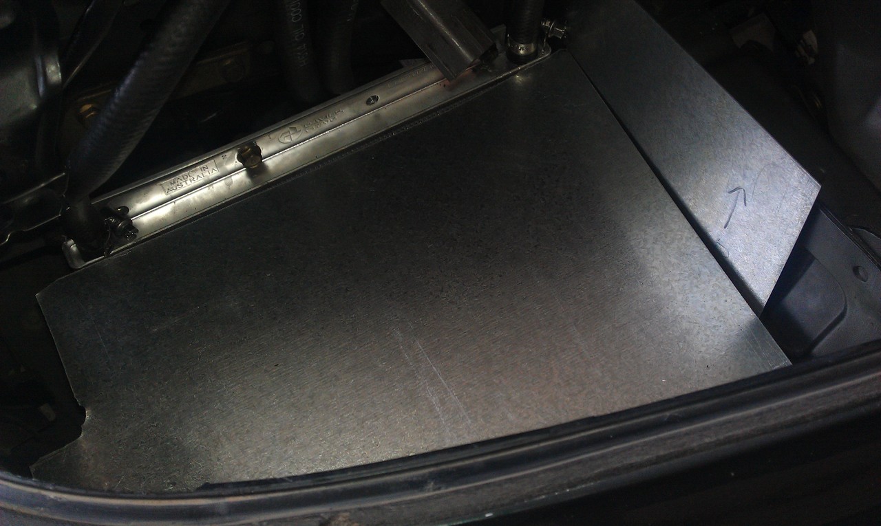
I started by removing all of the center console and CCS / stereo system so that I could begin 'modifying' the transmission tunnel on the Cosmo so the ratchet cable can go through the floor. I used a 13mm drill bit to start the process and then a die grinder with a carbide-tungsten bur to increase the diameter of the hole.

Here is a better of look at where to drill...

IMAG0393.jpg


You will need to drill through the plastic, through the floor of the car & then through two separate heat shield layers to get to the outside of the car. You will also need to drill at an angle - approx 30 degrees as the shifter cable needs to be as straight as possible as it leaves the shifter. This is where having a die grinder is a must. I should also add that you should not bolt the shifter in just yet as it makes it impossible to slide the cable through.

You will also need to trim the carpet back in this section of the car. Do not try and drill through it!

IMAG0394.jpg


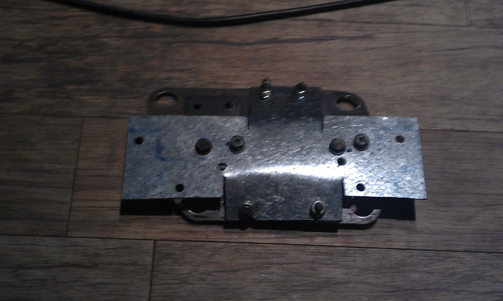
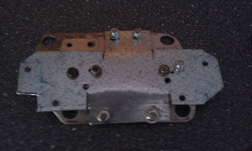
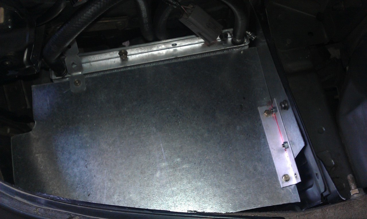
Above is the hole before I painted & siliconed it. I used some extension bars to massage the holes so that they had the best alignment.

The next step is to jack the car up, go underneath and remove the exhaust. I actually had a separate set of flanges installed so that I only needed to remove a very small section of the exhaust. Once the exhaust is off, you will need to remove the heat shield protecting the driver side of the gearbox. You will also need to remove the mounting points from the sump. Be careful when you do this and only remove one bolt at a time. Once you have removed each bracket, replace the corresponding sump bolt to avoid making a huge mess.

You now need to run the cable to through the floor pan. The easiest way to do this is to remove the 11/16 nuts from the end of the cable. Feed it down the passenger side of the box. Put your hand down the hole where the shifter used to be to help guide it. You basically want it to go straight down towards the ground.

Once it is through, it is time to bolt the other end to the shifter and then bolt the shifter to the trans tunnel. If you don't do this now, you will not be able to correctly align the shifter cable as it will want to rotate too much.

Get under the car & remove the upper heat shield which resides above the cats. Do not remove the whole thing, just the first two pairs of 10mm bolts which hold it in place. If you remove the whole thing then it becomes an uber pain the ass to put back if you are doing this by yourself.

The shifter cable needs to go back towards the rear of the car above the heat shield and then loop fowards on the drivers side so it is pointing fowards on the drivers side of the box. The normal 5ft cable which comes with the B&M kit is perfect - no need to order something else.

This is pretty much the point of no-return. Remove the old, solid shifter linkage from under the car by removing the circlip. Leave the shifter cable dangling here for now.

There is a support bracket which holds the exhaust is place which needs to go on a diet in order to fit the new shifter linkage. Although this is a terrible picture, you can see where I have taken a large notch out of it...

IMAG0396.jpg


Once you have trimmed this piece, put it back on the car. Now you need to install the shifter brackets and linkage. Note that you will need to purchase some 25mm M6 bolts to do the job as well as some small washers to act as spacers. You could also try to die-grind the lip of the sump to allow the bracket to fit better, however I do not recommend this as the lip is designed to strengthen the sump pan.

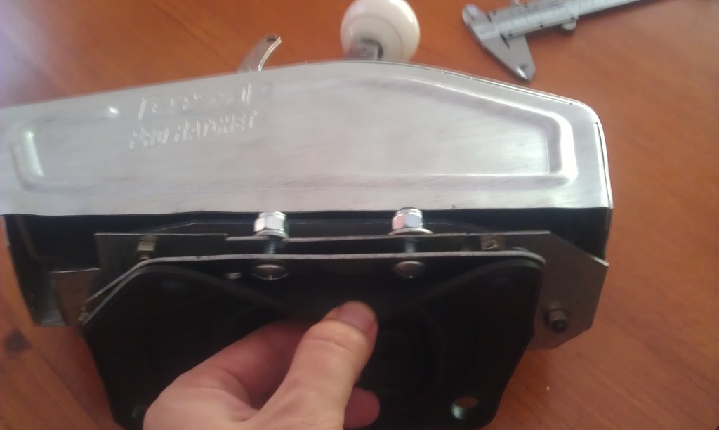
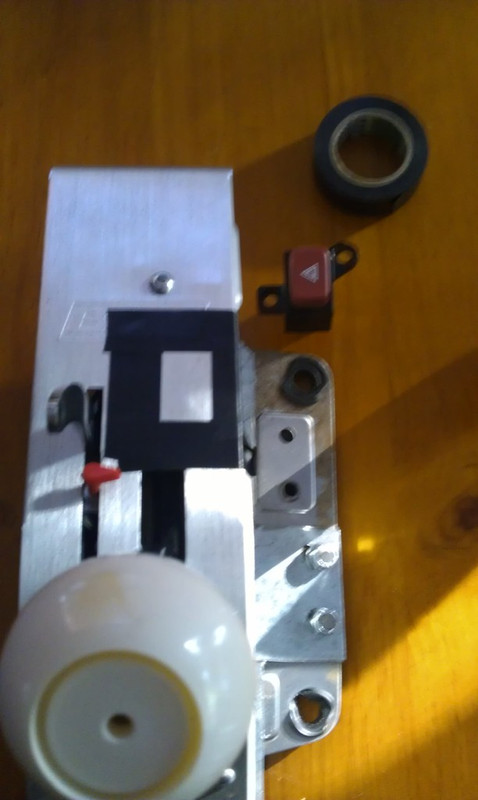
Here you can see the bracket and linkage installed.

IMAG0398.jpg


The cool thing about the standard box is that you don't need to cut off or remove the linkage on the box. The new linkage simply attaches over the top of the old one. Before hooking the cable up, ensure that the ratchet has had the 'park limiter' pin installed and is in the same gear position that you left the car in before removing the factory shifter.

Now the fun part comes.. adjusting the cable to ensure it goes into gear. I am not going to go into this here as there is a lot written about this already. My #1 piece of advice though is that this is a two person job. Get a mate to sit in the car and go through the gears while you (or your man servant) is under the car. Remove the linkage after every shift to ensure it is in gear. You will be able to feel this easily. In fact, the linkage will only come off if you have it properly in each gear. Adjust the cable using the 11/16th bolts as needed.

Once you are happy re-install the exhaust. Note that I could not find a good way to re-install the factory heat shield so I temporarily used heat-wrap on the exhaust until I could build something out of metal.

IMAG0397.jpg


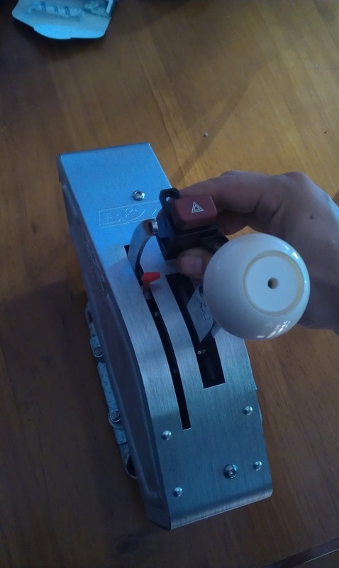
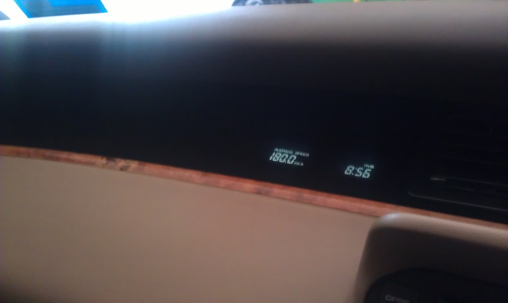
Here you can see it in the car... (excuse the mess!)

IMAG0402.jpg


To get it to fit like this you will need to trim the metal housing of the shifter. Use an angle grinder to cut the front and rear off the housing - yes completely cut it off. You will then need to use a die-grinder to cut away about 4mm of plastic off the front of the electric seat button assembly. Even trimming the metal casing down, you will still need to do this. You could move the shifter forward slightly also. I didn't realize though until it was already too late.

More updates to come.
 
Last edited:
The car goes in for it's transmission build tomorrow but before it went off the road again, I took it to the Brisbane Might Car Mods meet.

20910_574802045887820_798512826_n.jpg


602013_574802085887816_1399527087_n.jpg


9943_574804422554249_435723552_n.jpg


Back to the transmission, I noticed something very odd. When I had the Microtech installed the car had a pretty poor cold start. In most cases, I would need to use the accelerator to help kick the car over. It would start off the key but then die immediately if I didn't give it a bit of fuel. I had always put this down to the Microtech and the rep that they have for having terrible cold start settings. It turns out though that the reason the car was doing this had nothing to do with the ECU at all...

After removing the factory shifter, the car starts first time, every time off the key. After having a bit of think about it, maybe the reason it always died after the key start was due in part to the neutral safety switch. However as the shifter doesn't contain the switch, I am pretty confused about it.

The shifter contains a number of circuits. I wouldn't be surprised if one of the safety features was causing the car to stall.
 
If anyone is keen on an RE-Amemiya bodykit then shoot me a message! I'll be selling mine shortly.
 

Latest posts

Back