That doesn't sound right. I think you want to put the resistor on the blue of the MPI and then to a ground. Have the violet to the ecu side of #88. Still not 100% on this one. PM nick.Kooldino said:from Nick's install instructions:
"Install the MPI Tuner wire #18 violet to the PCM side #88 wire."
So you're saying put the resistor on wire #18 (violet) on the MPI, and then to ground. Also hook up wire #88 to wire #18 on the MPI?

You are using an out of date browser. It may not display this or other websites correctly.
You should upgrade or use an alternative browser.
You should upgrade or use an alternative browser.
MAF limit reached @ 14psi
- Thread starter Kooldino
- Start date
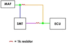
The first time I tried to start the car today, I had it hooked up like so:
wire #88 on the engine side -> resistor + black & white wire
I had the resistor sharing a ground with the MPI
I had the ECU side of wire #88 connected to the purple (violet) wire from the MPI tuner.
The car would start and immediately die.
Ok, putzed around for a minute. Changed it like so:
wire #88 on the engine side -> (resistor + blue wire) + black & white wire + green & yellow wire
I had the resistor sharing a ground with the MPI
I had the ECU side of wire #88 connected to the purple (violet) wire from the MPI tuner.
My MAP sensor was taken out of the loop completely, since it used to go into the black & white wire.
Previously my blue wire and my green & yellow wire were not used, this is the first time they had been hooked up.
It was running like crap. To top it off, I hate tuning with the MAF. You have to set your transition point from vacuum to boost by picking out a number between 0-5v (the AMP column). In general, if i set that number to 3.1v, it would coincide with me going on boost. So in layman's terms, once the MAF gave me a signal of 3.1v, it told the MPI tuner that I was on boost, and that it should start using my fuel maps now.
Here's the problem with that. If I'm in 4th gear @ 2000rpm and go WOT, i will build boost. However, the MAF will not show 3.1v yet. More like 2.6 or so. So I'd be on boost, but I wouldn't get any extra fuel yet.
Here's another problem I had. With the same setting of 3.1v, i revved the car out to redline at ~30% throttle position. At that throttle position, I was able to effectively rev out the car and never build boost. At the higher RPMs of that throttle position, the MAF was putting out ~3.5v. In other words, the MPI now thought that I was on boost (since the 3.5v is > than the 3.1v it was set for), and was now obeying my fuel maps. Problem was, I wasn't buildling boost. Needless to say, I ran SILLY rich, to the point of stumbling.
Now sure, you could say that at that particular throttle position, I could have simply not added fuel. But that's no good. Because in other gears at that throttle position, i AM in fact building boost. So my choices are: either run really rich off of boost at that particular throttle position, OR run really lean ON boost in that particular throttle position. Either will suck.
After I read Tim's last post about putting the #88 wire with the resistor into the blue MPI wire, I got the idea that the BLUE wire on the MPI is what clamped the MAF voltage.
So I figured that whatever was hooked up to the black & white wire is what the MPI tuner would use in the AMP column (where I previously had my MAP and now had my MAF).
I assumed that whatever was on the blue wire is what was going to be clamped, and sent out of the MPI via the purple wire.
As for the green & yellow wire...well, I couldn't figure out what that did. So I unhooked it.
So it looked like:
wire #88 on the engine side -> (resistor + blue wire) + black & white wire
I had the resistor sharing a ground with the MPI
I had the ECU side of wire #88 connected to the purple (violet) wire from the MPI tuner.
Turned it over, fired right up, ran normally. Ok, so it seems like the green & yellow wire didn't affect anything.
With my previous logic that the blue wire was an input to be "clamped" and output by the violet wire, I figured I'd take a stab at taking the MAF off of the black & white wire, and putting my MAP sensor back in there, since it was easier to tune. I did so.
So it looked like:
wire #88 on the engine side -> resistor + blue wire into the MPI.
MAP sensor -> black & white wire
I had the resistor sharing a ground with the MPI
I had the ECU side of wire #88 connected to the purple (violet) wire from the MPI tuner.
That's how it sits right now.
It behaves a lot better, and SEEMS to be clamping my MAF voltage, as I haven't yet got a "MAF Input Voltage too High" CEL.
My only issues now are this:
1-my maps are now a bit too lean under boost. My GUESS is that the resistor has something to do with this. I started fixing it, but they're FAR from perfected yet.
2-This has been a problem with ALL of the above configurations. Between 1K and 2K rpm, at light throttle positions, my A:F ratio goes through the ceiling. 17:1 or LEANER. Once I hit 2K RPM, it's all good. I want to blame the resisotr here too.
Any advice at this point?
It kinda sounds like it is right, except I don't know anything about the MAP. Before you go out and tune with a lot of boost, you really need to double check with Nick. We can't have that thing getting hurt.
You could try to have it going to it's own ground. I don't know if it would affect the MAP and all. Just try it to a bolt on the body somewhere.
As for the lean under 2k, it could be that since you put the resistor in, the ECU is "seeing" a lower voltage and thus not giving enough fuel. The car will idle (in warm condition) at around 2.0v. If you are idling anything lower, that could cause your map to be out of wack. Since I don't have any experience with the MAP, that could also be causing an issue. Once again, check with the expert!
Little Beavis
Member
- :
- 2001 MP3-T (#911)
Is there an abridged version of that post? Damn!
The resistor will affect the voltage (obviously). You can compensate for that by adjusting the fuel calibration if you so desire (that should adjust everything at once). Instead you're obviously taking it square by square. So, it looks like you need to adjust them all (especially the 1-2k range apparently).
Datalog the thing and you can see the input and output voltage. That will tell you for sure if it is clamping the way you want it to.
What kind of resistor did you use? .5 or .25w?Little Beavis said:Is there an abridged version of that post? Damn!
The resistor will affect the voltage (obviously). You can compensate for that by adjusting the fuel calibration if you so desire (that should adjust everything at once). Instead you're obviously taking it square by square. So, it looks like you need to adjust them all (especially the 1-2k range apparently).
Datalog the thing and you can see the input and output voltage. That will tell you for sure if it is clamping the way you want it to.
My fuel zero calibration has always been 8. I tried to turn it down to a 0 like yours, but the car died immediately. I have no idea why it's 8. So should I turn that up?
Ok, now I'm terribly confused. Last night I took the car for a spin, and while it had the usual 500-2000rpm lean spot, it ran fun at WOT, all the way through the rev range.
Drove to work this morning...and now it drives like crap, often hitting 19:1 AFR and sometimes stalling. It likes to go way lean (and then way rich) all the way to 4000rpm. But other times, it behaves. Usually not though. And it only misbehaves during accelleration.
BinaryRotary
Member
- :
- 03 MSP, 85 RX-7 GS, 90 RX-7 TII
Cool beans.
Start tuning the car. Calibrate your sensors so you only read boost. Then you can get the timing retard and boost load fueling to work right. You need to tune with the AEtemp scale, this is boost load.Kooldino said:The first time I tried to start the car today, I had it hooked up like so:
wire #88 on the engine side -> resistor + black & white wire
I had the resistor sharing a ground with the MPI
I had the ECU side of wire #88 connected to the purple (violet) wire from the MPI tuner.
The car would start and immediately die.
Ok, putzed around for a minute. Changed it like so:
wire #88 on the engine side -> (resistor + blue wire) + black & white wire + green & yellow wire
I had the resistor sharing a ground with the MPI
I had the ECU side of wire #88 connected to the purple (violet) wire from the MPI tuner.
My MAP sensor was taken out of the loop completely, since it used to go into the black & white wire.
Previously my blue wire and my green & yellow wire were not used, this is the first time they had been hooked up.
It was running like crap. To top it off, I hate tuning with the MAF. You have to set your transition point from vacuum to boost by picking out a number between 0-5v (the AMP column). In general, if i set that number to 3.1v, it would coincide with me going on boost. So in layman's terms, once the MAF gave me a signal of 3.1v, it told the MPI tuner that I was on boost, and that it should start using my fuel maps now.
Here's the problem with that. If I'm in 4th gear @ 2000rpm and go WOT, i will build boost. However, the MAF will not show 3.1v yet. More like 2.6 or so. So I'd be on boost, but I wouldn't get any extra fuel yet.
Here's another problem I had. With the same setting of 3.1v, i revved the car out to redline at ~30% throttle position. At that throttle position, I was able to effectively rev out the car and never build boost. At the higher RPMs of that throttle position, the MAF was putting out ~3.5v. In other words, the MPI now thought that I was on boost (since the 3.5v is > than the 3.1v it was set for), and was now obeying my fuel maps. Problem was, I wasn't buildling boost. Needless to say, I ran SILLY rich, to the point of stumbling.
Now sure, you could say that at that particular throttle position, I could have simply not added fuel. But that's no good. Because in other gears at that throttle position, i AM in fact building boost. So my choices are: either run really rich off of boost at that particular throttle position, OR run really lean ON boost in that particular throttle position. Either will suck.
After I read Tim's last post about putting the #88 wire with the resistor into the blue MPI wire, I got the idea that the BLUE wire on the MPI is what clamped the MAF voltage.
So I figured that whatever was hooked up to the black & white wire is what the MPI tuner would use in the AMP column (where I previously had my MAP and now had my MAF).
I assumed that whatever was on the blue wire is what was going to be clamped, and sent out of the MPI via the purple wire.
As for the green & yellow wire...well, I couldn't figure out what that did. So I unhooked it.
So it looked like:
wire #88 on the engine side -> (resistor + blue wire) + black & white wire
I had the resistor sharing a ground with the MPI
I had the ECU side of wire #88 connected to the purple (violet) wire from the MPI tuner.
Turned it over, fired right up, ran normally. Ok, so it seems like the green & yellow wire didn't affect anything.
With my previous logic that the blue wire was an input to be "clamped" and output by the violet wire, I figured I'd take a stab at taking the MAF off of the black & white wire, and putting my MAP sensor back in there, since it was easier to tune. I did so.
So it looked like:
wire #88 on the engine side -> resistor + blue wire into the MPI.
MAP sensor -> black & white wire
I had the resistor sharing a ground with the MPI
I had the ECU side of wire #88 connected to the purple (violet) wire from the MPI tuner.
That's how it sits right now.
It behaves a lot better, and SEEMS to be clamping my MAF voltage, as I haven't yet got a "MAF Input Voltage too High" CEL.
My only issues now are this:
1-my maps are now a bit too lean under boost. My GUESS is that the resistor has something to do with this. I started fixing it, but they're FAR from perfected yet.
2-This has been a problem with ALL of the above configurations. Between 1K and 2K rpm, at light throttle positions, my A:F ratio goes through the ceiling. 17:1 or LEANER. Once I hit 2K RPM, it's all good. I want to blame the resisotr here too.
Any advice at this point?
Thanks again
Later............Nick
Which sensors? the MAF? What voltage should I use?MPNick said:Start tuning the car. Calibrate your sensors so you only read boost.
Then you can get the timing retard and boost load fueling to work right. You need to tune with the AEtemp scale, this is boost load.
the sensor calibration settings.Kooldino said:Which sensors? the MAF? What voltage should I use?
Thanks again
Later.............Nick
That didn't answer my questions.MPNick said:the sensor calibration settings.
Thanks again
Later.............Nick

Dunno, didn't try it yet. Gotta fix http://www2.msprotege.com/forum/showthread.php?t=70328 before I move on.
New Posts and Comments

- Replies
- 134
- Views
- 9K
- Replies
- 1
- Views
- 168
