My new MAF setup + extra pictures

Spooled said:
Anyone check to make sure that the loss of power isn't coming from the ECU pulling timing? Just an idea.


Good call. I will have to look into this. I had thought about getting a larger MAF so I will have to pursue this a bit more now cause this seems like a very plausible explanation for the loss of power. All the air is accounted for, but our MAF which has not been recalibrated for the extra flow, is now seeing all of this pressurized (read: faster flowing) air that it is not used to seeing. The ECU thinks that the car is working like a dog when in fact it isn't and it pulls some timing to settle down the party. You thinking something along those lines?

R
 
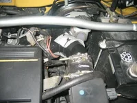
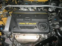
Here are some pics of my new setup. Wish that I had dynoed it before I made the changes becaused it would be nice to know how the setup changed the flow and power of the motor. Especially since I change two things during this round of tinkering.

Background: Previously, had all 2.5" piping for the intercooler and the MAF was in its pull-thru position on the CAI. I recirculated with the stock BPV without a second BOV venting atmospheric. The last mod prior to this change was the custom 3" J-pipe. I had noticed great response and top-end gains (all via butt-dyno) with this change. I was concerned about a 90 degree bend immediately prior to the FMIC since the 2.5" was a tight fit and I hadn't wanted the frame cut. I wanted to change to 2.5" piping that had a more natural path to the FMIC inlet.

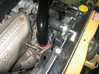
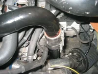
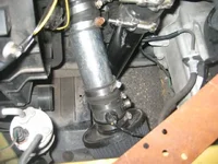
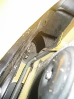
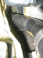
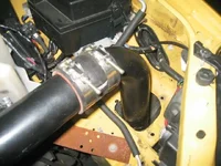
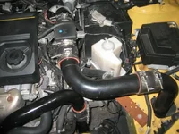
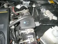
Changes made: 2" mandrel-bent piping (turbo-IC) now routed underneath the frame rather than in front of the rad. MAF moved to the pressure side, ~12" after the outlet for the BPV and ~12" before the TB. IAT wires extended and IAT left adjacent to CAI in bottom of engine-bay.

Impressions: After resetting the ECU, the car ran perfectly. No hesitations, no stalling at stops. It ran smooth as stock. It also spooled faster (likely the change to the piping diameter). AFRs stayed the same at ~14.x. EGT was about the same, perhaps a bit lower. However, it felt like it had lost some power. Accelerating under WOT did not feel as frenetic or angry. Pipes causing this or MAF position? I suspect both. However, when I thinik about the MAF position a bit more I suspect the MAF more than the piping, and I think that the ECU may be pulling timing.

Granted, all the air that is in the system is measured by the MAF in this position. However, now that the air is moving by the sensor quicker it is more likely to cool the element (MAF uses temp differential between IAT and MAF to determine airflow) than slower moving air in the CAI. My FMIC is pretty efficient so the IC-TB air is pretty cool to begin with. The pressurized flow only exacerbates this issue. With the IAT in the stock position, the gradient in temp between the MAF and IAT is now alot larger than it otherwise would be. I haven't checked the MAF voltage under WOT, but I bet that it reaches max long before WOT now.

I haven't read the whole thread so it may have been said before, but I bet that moving the IAT to the IC-TB pipe somewhere before the MAF would alleviate the problem to a large degree. I am not sure how the IAT sensor would stand up to the pressurized flow, but the temp gradient would be less steep and the MAF would be less likely to intervene.

I'll attach pics below.

R
 
1. 2" turbo-IC pipe
2. as above running down behind CAi
3. CAI with IAT
4. 2" turbo-IC pipe as it peeks up from underneath frame and curls around to IC inlet
5. IC-TB pipe exiting FMIC
 

Attachments

  • IMG_3699.webp
    IMG_3699.webp
    39.2 KB · Views: 232
  • IMG_3700.webp
    IMG_3700.webp
    36.4 KB · Views: 219
  • IMG_3701.webp
    IMG_3701.webp
    35.7 KB · Views: 234
  • IMG_3702.webp
    IMG_3702.webp
    23.9 KB · Views: 199
  • IMG_3705.webp
    IMG_3705.webp
    19.6 KB · Views: 200
More pictures

1. IC-MAF pipe coming up through fender well. Note that the frame was cut here a bit.
2. as above showing MAF connection
3. MAF connection
4. MAF-TB pipe
5. engine bay snapshot
 

Attachments

  • IMG_3706.webp
    IMG_3706.webp
    35.1 KB · Views: 227
  • IMG_3707.webp
    IMG_3707.webp
    43.6 KB · Views: 226
  • IMG_3708.webp
    IMG_3708.webp
    34.1 KB · Views: 201
  • IMG_3709.webp
    IMG_3709.webp
    41.1 KB · Views: 216
  • IMG_3710.webp
    IMG_3710.webp
    41.1 KB · Views: 228
BTW I am also building a larger MAF to see whether this will help matters.

R
 
I note on the IAT. I don't think that it would be damaged if it were placed on the pressure side, but you would need a way to mount it so that it doesn't pop out like a cork under pressure.
 
see how you have the iat in a coupling at the filter, relocate that to the charge side and use silicone glue or something to keep the sensor in place.(check temp range to make sure the sealant can stand up to boosting temps) Mine ran fine like that, when I wanted to boost over 10-12ish I put the iat near the motor outside the charge pipe to retard timing.
 
jeffmsp said:
see how you have the iat in a coupling at the filter, relocate that to the charge side and use silicone glue or something to keep the sensor in place.(check temp range to make sure the sealant can stand up to boosting temps) Mine ran fine like that, when I wanted to boost over 10-12ish I put the iat near the motor outside the charge pipe to retard timing.

Been racking my brain trying to figure out what kind of fitting I can use to keep the sensor put. I'll have to scout my local fitting store to see if I can come up with something creative that doesn't look completely ghetto fab.

R
 
Ryoga28 said:
Can you tell me what silicon reducers were used? where did you mount the temp sensor (intake or next to the maf)?


drilled new hole right behind the filter and put the rubber gromet there fits perfect
:)
 
Rainman said:
Been racking my brain trying to figure out what kind of fitting I can use to keep the sensor put. I'll have to scout my local fitting store to see if I can come up with something creative that doesn't look completely ghetto fab.

R

It's not worth it drilling holes. I've tried various setups with the IAT sensor in various possitions, and pretty much the outcome was all the same. Right now my IAT sensor is just hanging in the hole where the CAI goes. It's been like that for over 30k miles, and nothing has changed.

If you're interested in checking out the different behaviors which are possible with different IAT temps, just replace the sensor with a variable resistor (forgot the official name) and approximate the temps with different resistance...that's all the IAT sensor does. Ofcourse you'll need a digital multimeter.
 
CustomMSP said:
It's not worth it drilling holes. I've tried various setups with the IAT sensor in various possitions, and pretty much the outcome was all the same. Right now my IAT sensor is just hanging in the hole where the CAI goes. It's been like that for over 30k miles, and nothing has changed.

If you're interested in checking out the different behaviors which are possible with different IAT temps, just replace the sensor with a variable resistor (forgot the official name) and approximate the temps with different resistance...that's all the IAT sensor does. Ofcourse you'll need a digital multimeter.

You gave me an idea. No drilling required (at least not in my hardpipes). Check out pic 1 in my second set of pics. There is a connection right after the pipe comes out of the fender well. If I inserted a short piece of pipe (it could even be high pressure PVC piping as suggested in Autospeed for a rebuilt MAF) I wouldn't have to do massive modifications to my setup. Here the sensor would then be sensing air before the MAF that was also pressurized, rather than unpressurized ambient air. This air (leaving the FMIC) would already be cool and moving at speed, but the IAT would read this as ambient. Then when it read the temp at the MAF the temperature differential between the IAT and MAF would be less. In addition, the differential would be solely because of engine demand for oxygen/air since the air at the IAT and the MAF are both pressurized, thus moving at speed, therefore allowing the speed of the airflow attributable to the turbo alone, to be ignored since it is represents a baseline flow present at both sensors. s***, that is a mouthful. Anyway, now that I've found a place for the sensor, I just got to do it.

Of course, if my MAF upgrade experiment is successful, I could simply extend the length of the MAF body to include a port for the IAT sensor, before the MAF heating element.

R
 
CasopoliS said:
Moved the MAF. My setup is described in the first picture below. The car pulls like none other... and there isn't any hesitation. We will have to see how long the MAF lasts. A blow by MAF will be ordered just to make sure, and my Apexi air filter is next. I am extending the filter to the corner with an alum. extension, and drilling a hole in the extension for the IAT. I already have the extension (cut from CAI portion of the Injen). Thanks for lookin... still needs waxed.

turbosetup017nx.jpg
(braindead
Got some questions...

1: Why are you waiting to see how long the MAF lasts From the heat?
2: And why are you still BOV'in and recirculating I would think since the MAF was moved you would only need to do one or the other...

~Forgive me if this was talked about here already...(poke)
 
1. because it wasnt designed to be on the charge side, we are concerned it may become damaged since it is such a delicate instrument.
2.dual valves are unneccessary when you relocate the maf, not sure why he would keep it dual, maybe he likes the sound.
 
MazdaSpeedSter said:
2: And why are you still BOV'in and recirculating I would think since the MAF was moved you would only need to do one or the other...

~Forgive me if this was talked about here already...(poke)


Although there is no need to recirculate with this setup, you will get better response with the recirculating setup. I believe that Corky Bell agrees with this sentiment in his book, and a recent article in the mag "DSport" (? or D-Something-or-other) suggests the same.

R
 
isnt the point of a bov to improve responciveness compared to the stock bpv? Why would it work better to vent only half the air? wouldnt it make more sense to just run an adjustable bov then.(which alot are)
 
jeffmsp said:
isnt the point of a bov to improve responciveness compared to the stock bpv? Why would it work better to vent only half the air? wouldnt it make more sense to just run an adjustable bov then.(which alot are)

I will look up the reason why and get back to you.

R
 
ok just so that i get this right, i just move the maff to turbo tb side right...? cut right through turbo to tb pipe and then mount maff in their right...?
thanks

-dave
 
doggman said:
ok just so that i get this right, i just move the maff to turbo tb side right...? cut right through turbo to tb pipe and then mount maff in their right...?
thanks

-dave
^^^ Yep. That is about it. It would be best if you could mount your IAT sensor in the path of the MAF in the IC to TB pipe, however, I haven't gotten around to doing this part myself yet. With the IAT sensor so far downstream from the MAF you might find a small decrease in power over what might have been obtained with your other mods. Dyno data would be the way to confirm this loss..

R
 
Back