MSP FMIC by Wagnermotorsports

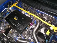
Questions about kit (I know the pictures aren't for final product).

1. Now that the MAF is going to be in the I/C_T/B pipe is this going to cause premature wear of the MAF sensor? I know someone here in Vegas who has this done, BLURSPEED, and he's had no problems but I want to know your opinions about our MAF sensor and if it can hold up to air going both ways.

2. Second. Will it not even matter about the air going both ways if you have the BOV in there. I mean, correct me if I'm wrong, even if you have all this extra air in the system then close the T/B, won't the BOV just get rid of the air before it has chance to hurt the MAF. If this is true then why wouldn't you mount the BOV in between the MAF and the T/B.

Again from the looks of the pictures it looks like your going to have the BOV_MAF_T/B, in that order when wouldn't you want it to be MAF_BOV_T/B that way you don't have to worry about the air ever going back into the MAF it will only go one way and we won't ever have to worry about this again.

omments on this would be great. Thanks. John (Las Vegas)
 
Last edited:
The kit looks great guys, especially the new endtanks. From the pics that I saw it looks to me like the injen WILL go underneath the IC piping. Not positive but wanted to point that out.
 
The MAF is going on the intake pipe, not the pipe from the IC to TB. :D That is a coupler there.

I would not suggest putting the MAF on the charged side of the Turbo, for the simple reason, its not a 2 way MAF. Air is supposed to gon 1 way only through it. Putting forced air though it one way WILL wear it out quickly, and cause failure.
 
two questions:

1) is there any cutting involved?

2) is there a reason why the kit doesn't use hump hose connectors in some places to allow for engine movement? i understand the stock motor mounts aren't the greatest...
 
Boostisgood: Can you post final pics when your done or is Wagner going to post them on the site. I would really like to see this final product (like everyone else I know I know). thanks....awesome looking kit. Thanks for answering my questions.
 
I may be interested as well. i am waiting to hear from ION, but if I hear something from you first I might change my mind, especially if yours will ship faster.
 
The kit will be finished and installed on the 20th. :D I will try to get pics uploaded, but Im sure Andrew will do the same. There is NO CUTTING INVOLVED. There is a hump hose on the TB, to allow for engine flex. :D
 
MSP_HK said:
What kind of pipe is this made out of for these kit??
stainless steel.. im not sure the grade, it is probally listed somewhere. The finished product will look awesome.

here is a pic of my piping.. im sure the finished product will look similar (not in design).
 

Attachments

  • 101_0162.webp
    101_0162.webp
    63.7 KB · Views: 288
Wow look like some real qulaity Front mount. But it doesnt leave much room in the engine bay. I was thinking of buying the equal length manifold from Husker so I dont think it will fit. But this is good stuff. I like the size of that innercooler.
 
boostisgood said:
Ok, we could not finish the prototype kit yesterday, due to inclimate weather. (Its a 3 hour drive for me each way) Andrew has the IC built, and it is installed on my car. We need to finish the piping for the kit, and thats it. :D

First, the final pricing for the kit, as what I know of right now, has not been set. This kit is going to be MUCH different then the other FMIC upgrade kits, and will have ALL numbers to back up its importance.

As far as numbers, I do know the Spearco IC is 3 inches deep, by 7 inch, by 15 inces. (correct me if im worng andy) It will flow 600 CFM, which the little t-25 would never max out. This IC is a bar and plate, unlike the stock IC, which is a tube and fin.

Now let me mention about Nick (perfworks) and Andrew (wagner) These guys are great. Full of knowledge, and really intense when doing thier work. I spent the whole day at the shop yesterday, and helped them out a bit with the car. I learned some new things, and got ALOT of stuff cleared up for me. :D These are great guys, and working on providing us great products.

Finally, here are some pics of the IC, and other random pics.

Andrew taking some measurments
meansure.jpg


Here Andrew and Nick (perfworks) do some measuring inside the front bumper.
andrewnnick.jpg


A pic of the IC installed, without the bumper.
installed.jpg


A pic with it installed WITH bumper. Nice fittment
installedwbumper.jpg

the stock tube and fin IC against the Spearco Bar and Palte IC
stockvwagner.jpg


I will explain the piping, once they are done, and installed. I would need to show the pics, for you to understand how they will install. :D

Look for the kit to be finished within the next 2 weeks. (as soon as I can get back there)
That looks nice!!!
 
Was there any noticable differences in throttle response, turkey or anything?
 
Last edited by a moderator:
Looking at your pictures i see there are no hose connectors. Would you reccomend getting AWR motor mounts before doing this install? Couldnt engine movement crack the welds and possibly create a leak?
 
mattybo said:
Looking at your pictures i see there are no hose connectors. Would you reccomend getting AWR motor mounts before doing this install? Couldnt engine movement crack the welds and possibly create a leak?
the one that connects the pipe to the throttle body allows for movement, also all the rubber cuplings allow for some movement as well.

upgrading your mounts, at least the front one, would be a good idea regardless.
 
Back