Moonroof & Driver side switch

nice, thanks so much, that will really help!

Since you placed one moduler on the passenger side. Will the one-touch work for both the passenger side (window button) and the driver side (passenger button on master panel)
 
Ok, if you look a the moonroof schematic...(Thanks zul114)

All the switches work of a ground connection, the switches drive relay's, rather then the actual window motor.

The good part about this is that no matter what combo you do, you can't short out anything or blow any fuses.

So all you need to get an auto-open to work is to ground the Open button until the window is opened.

The extra bonus, is that the moonroof already has limit switches built-in.
Meaning once the roof is open, the relays and switches kick themselves off.

So, all you need is a single relay to make an auto-open moonroof:

I will get a diagram up in a minute
 
Here is the diagram:

attachment.php


Ok: looking at the diagram that Zul114 posted:
The Open switch is connected to Pin 1D

You need to locate this wire and cut it in two.
The wire coming from the Motor/relay assembly runs to one side of the relay coil.

The other side of the relay coil runs to the sunroof switch panel (1D)
This same wire also connects back to one of the relay's switch terminals.

The other terminal on the relay runs to a ground connection (or tapped into 1F on the switch panel)

When you press the OPEN button on the switch panel, the relay will close, and the moonroof will start to open.
The relay will self-latch, keeping the moonroof opening, without you having to press any buttons.
Once the moonroof is fully open, the limit switch kick's in, and cuts the power, causing the relay to reset.

You can then close the moonroof however you want.

This same circuit would work for auto-close, or up, just splice another into the switch panel.
 

Attachments

  • Automoonroof.webp
    Automoonroof.webp
    13.7 KB · Views: 898
zap> Is this going in right after the switch? if that's the case, it's REALLY easy to find, I've tapped into mine there already with my relay setup. My deal, though is that my alarm has options for timers and I set it at 8seconds which is just about right to get full-open. I'd assume this form of relay wiring would work as well for my purpose inwhich case I can change my alarm to pulse which I'd be mroe comfortable with.

screwit I'll go pull my stuff apart and show how I wired, and got into everything when it cools down (it's over90 here rightnow, and I've got no shade to even work in)
 
okay, just took a closer look, that lcoation is exactly where I'm curently tapped into, however I simply tapped into it instead of cuttingthe wire and putting the relay between...

Also I'm a relative moron, could you possibly breakdown what wire needs to go where on the relay itself? I think I'm going to do this atleast for the open function. the close might be trickier as I've currently got both running off of a single relay/channel in my alarm. Basically I've got 3 channels and 4 functions, so close does both. Also I really don't know howmuch more room I've got. Fitting 3relays wasn't too hard, though.
 
Tapping the wire works for an timed controller.
But you have to cut into the wire to get the latching relay to auto-reset.
Basicly the entire circuit is in series, once the limit switch cuts off the power, the relay resets.

Let me get a diagram for the relay up...
 
http://www2.msprotege.com/forum/attachment.php?attachmentid=21449&stc=1


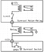
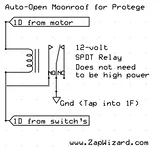
Ok, this is the same diagram, without the extra circuits that are in the car.

You will make three connections to the car wiring:
1:) Ground (1F on the switch panel)
2:) 1D from the motor/relay assembly
3:) 1D from the switch panel

Basicly the relay is spliced into the 1D Wire.

1D from the motor/relay assembly is wired up to one side the relay coil.
(It doesn't matter which side of the coil)

1D from the switch panel is wired to the other side of the relay coil.
Then a wire is ran from this side of the relay coil, back onto the switched terminal on the relay. If the relay is Double Throw, then you need to connect to the normaly open (NO) side of the terminals.

The middle switched terminal on the relay is then wired directly to ground.
Or you can tap (don't cut) it into the 1F wire from the switch panel.

The parts list for this mod:
1x SPST relay (normaly open type) or a SPDT relay
3x Wire tap's
1x Wire

It don't get much simpler then that.

The relay doesn't need to be high power, only 12volts.
As the relay is not working the motor's directly, but working another relay.

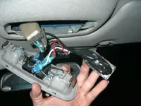
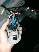
Poseur, do you know of a guide on taking apart the roof to get to the circuits?
Or should I just follow the service manual?

As I can make a total step-by-step guide with photo's, but I can't be without my car for more then an evening.
 

Attachments

  • untitled.webp
    untitled.webp
    12.7 KB · Views: 435
As far as getting into the wires in question it's as simple as just yanking the light/switch assembly out. there's a couple spring-clips holding it in... I recommend you grab it from either the left or right side, and just yank hard, it'll come eventually. Here are a couple pics of my setup. I can't remember how I wired the relays, it was simple enough, though. basically the black speakerwire that comes in is the signal wires from the alarm. The wires are located respective to their positions on the switched, but to simplify it all here's the breakdown:
(all wires have res spots on them)

1D-Blue: slide open
1E-Blue/Wht: slide closed
1B-Blue/Yel: tilt up
1C-Blue/Grn: tilt down

1F-Black: ground

There are also a couple of power wires:
2A-grn/orange: +12v
Blue/red +12v (unrelated to sunroof, is used for lighting, but this is an unswitched power source if needed)

The system for the lights works off of grounding as well, so when the light is off the black wire corresponding shows positive voltage, and is only grounded once you push the button for the light.


Space is tight up in there, so t-taps were necessary for me. however if you're cutting into the wires, there's room to solder SOME of the connections nicely. (cordless soldering iron+light colored headliner=potential burnmarks so watch out) I tried to include a picture that shows where my relays are tucked into... There's a seam at the front of the roofline wher ethe flat "tail" of a relay will very nicely snugly slide into and not move (I have some 2-sided tape on them as well that's still got most of it's plastic backing, only a bit of the sticky part is being used in case I ever need to get them out, for things such as this...
 

Attachments

  • P1040003.webp
    P1040003.webp
    47.2 KB · Views: 231
  • P1040004.webp
    P1040004.webp
    57.7 KB · Views: 211
  • P1040007.webp
    P1040007.webp
    33.1 KB · Views: 218
Last edited:
Oh, yea, and Zap, thanks, you ARE the man.. I think I'll try this new method soon and report back. unfortunate side isthat I've soldered all of my wires into my relays, so I'll have to get mroe relays to make this happen.
 
your awesome thanks for all the help, i was really looking forward to that, now all I need to do is wire it.

Thanks
 
zul114 said:
nice, thanks so much, that will really help!

Since you placed one moduler on the passenger side. Will the one-touch work for both the passenger side (window button) and the driver side (passenger button on master panel)
I was just realizing i never replied to this, sorry. Yes, it does indeed make the driver and pass side switch for the window activate the module. If you tapped into the inputs before the pass side switch it would only be controllable one-touch from the driver's side and normal from the pass-side, but for one my g/f gets a kick outta it, and two, you've got to cut into a wire somewhere anyways, might as well get the most outta it.
 
Back