After a lot of research and trial and error I found a solution that I think works/sounds well. I had attempted this a couple years ago using an Audiocontrol LCi line output converter with Accubass and was never satisfied with how things sounded. This time around I swapped the Audiocontrol LOC out for a Kicker Key LOC and the difference is night and day imo. Back when I had first started this project I'd bought access to the Mazda repair info site and downloaded all the audio wiring diagrams. I ended up having/using the Mazda Connect Type B diagrams but I'll post both Type A and Type B after this post. Not going to go super in depth on things like running power and ground wire as there are many Youtube videos etc. on these topics. Primarily want to focus on the wiring/factory integration aspects. I'll start by listing the install parts/prices I used:
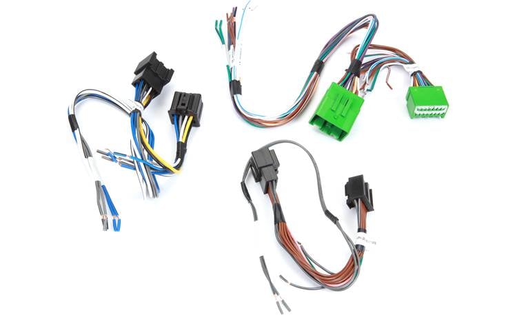
Wiring harnesses $34.99: you only need one of the harnesses (Black 16-pin) but if doing a broader install the others might be needed. The green 16-pin and black 16 pin connectors both fit the factory Bose amp but I didn't verify the other harness, will detail pin outs below:
 www.crutchfield.com
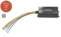
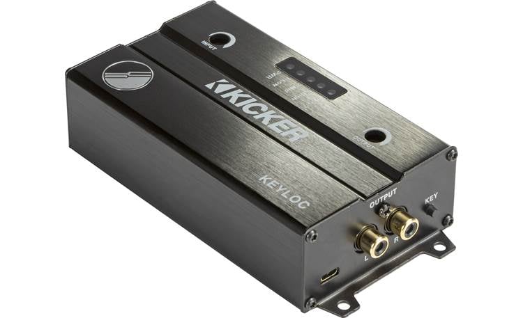
Kicker Keyloc $124.99: I used the Kicker Key 2 channel LOC in conjunction with an amp I already had. If you wanted to kill two birds with one stone, you could get the Kicker Key mono amp. The 2 channel LOC can be found here:
 www.crutchfield.com
JL Audio JD 250/1 $229.99: I already had this amp from a previous install. Amp/Sub choice are personal preference. JD 250/1 here:
 www.crutchfield.com
JL Audio 6w3v3 $299.99: Already had this sub from a previous install. Again, amp/sub combo are personal preference. These little 6.5" JL subs put out A TON of fairly accurate bass for their size. I used this because it fit perfectly in the wheel well. Sub here:

Sub Grill $34.99: self explanatory, here:

Amp wiring kit $64.99: I usually build my own wiring from scratch, but if buying a kit Knu Conceptz is my go to. Welding wire companies like Temco Industrial are usually the cheapest. Any oxygen free copper kit will do. Won't get into wiring gauge but generally a 4 gauge kit is a happy medium. Knu Conceptz 4 Gauge OFC kit here:

 www.knukonceptz.com
Short RCA interconnect cable $7: You could use the included one in a kit, but you only need 1-2 feet of length. 1 foot cable here:
Distribution Blocks $7: Not totally necessary. If using a Kicker Key mono amp, or if you were to do jumpers off the amp terminal for power and ground to the LOC you could skip these, just make sure you have an inline fuse before the LOC in addition to the main power wire fuse. I used a couple cheap ones like these:
Wire Ferrules $10: A mix of small and large ones is nice to have for your power/ground wires and your speaker output wires:
Flush Cutter $10: I absolutely love these for cutting zip ties:
https://www.harborfreight.com/5-in-precision-flush-cutter-57794.html
In line fuse $7: Again, only need this if using a separate Kicker Keyloc and amp. If using the Kicker Key mono amp you can skip these. The Keyloc calls for a 2 amp in line fuse:
Speaker Wire: Any old speaker wire will do, roughly 18 gauge.
Tesa Tape $8: Must have for wiring imo:
https://www.amazon.com (commissions earned)
Add a circuit $7: This is not necessary, but I prefer doing add a circuits for remote turn on. Most amps/gear nowadays have some form of signal sense/auto turn on, but I prefer to run a dedicated line. Could also tap a wire on the harnesses for remote turn on. I believe the fuse box in the cabin uses low profile mini fuses, but I had to use a regular profile mini add a circuit to make it fit correctly, like this:
Wire connectors/terminals $26 kit, insulated spade terminals $10: Mainly just need some butt splice connectors, some fork terminals, and some spade connectors. A kit like this has them all, only thing I prefer outside this kit is insulated spade connectors. Links here:
Wire Crimpers $20: Harbor freight has a nice pair here:
Wire Strippers $10: Any kind will do, some folks prefer ratcheting etc. Again HF has decent cheap ones:
Wire lug crimper $17: Super nice to have around for making your own power/ground wires.
Heat Shrink Tubing with Adhesive $16: I prefer the kind that's adhesive lined, but any will do:
Zip ties $4: https://www.amazon.com (commissions earned)
Wire loom: either braided or plastic split loom. Harbor Freight has cheap plastic split loom, or Amazon has rolls of braided wire protector. Not necessary, just makes for a cleaner install imo.
Amazon braided loom $15: https://www.amazon.com (commissions earned)
HF split loom $2: https://www.harborfreight.com/elect...-inch-x-10-ft-protective-wire-wrap-66987.html
Amp rack ABS or HDPE: Plenty of options, need enough to fit your amp/wiring so measure before hand. Plenty of options on Amazon or you can even using a plastic cutting board. Any plastic about 1/4" thick will suffice and roughly 2'x2' to cut to shape.
Rivet nut tool, rivet nuts, and bolts: I have an Astro Pneumatic one. Harbor Freight has a $50 kit that includes some rivet nuts. Grab a few bolts from a hardware store and you're set. Link to HF Rivnut tool here:
Drill/drill bits/driver bits: Self explanatory. Any drill and a set of small bits/drivers will do. Just need it to attach things to the amp rack.
I may have forgotten stuff but this should be mostly everything. A lot of this stuff you may already have on hand. Moving on to the install. I'll try and be as informative/concise as possible, again keeping in mind I won't go into too much detail on running power/ground etc.
Step 1: Disconnect your battery. Leave it disconnected while plugging/unplugging anything. You'll need it connected to move your passenger seat to remove the amp cover. Run your power, ground and remote wire. Removing the rear seat bottom there are plenty of spots to ground to. I made a little fuse holder for the engine bay like this:

Step 2: Prepare your integration wiring harness. This will avoid cutting/splicing any factory wiring. Using the wiring harness linked above, you're going to want to grab the black 16-pin harness that looks like this:

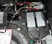
After removing the amp cover under the passenger seat, you'll end up disconnecting the same black 16-pin plug from the factory Bose amp. It looks like this (ignore the disconnected green plug/leave that connected):

Ignore the wiring labels that come on the harnesses. With the plug disconnected if you are looking straight on at the Bose amps female port/slot, the pin outs look like this:

On the PAC harness above with all the brown wires, you'll end up connecting crimping together the grey and grey/black stripe wires, and then for the other 3 channels you'll cut them in the middle, and add ~8 foot wire pig tails onto them. Do the wires one at a time and label them as you go if it helps. Make sure you are working on the male end of the plugs below, not the female end otherwise the wires will be reversed and it won't work correctly.
2.1: Start by crimping a butt connector onto one end of the grey/black stripe wire, slide your heat shrink on, and then crimp the other end of the grey/black stripe wire into the butt connector. This pin is not actually used so you could skip this but doesn't hurt to connect it.

2.2: Next, grab ~8 feet of speaker wire and strip the ends. Grab one end of the solid grey wire (Rear Left Door Speaker - ) and twist a bare wire end from your 8' speaker wire to it, make sure you keep straight which are you positives and which are your negative wires for later on. Insert both/2 wires into one end of a butt connector and crimp them in place. Slide heat shrink over, and then insert the other single grey wire into the other end of the butt connector and crimp it down.
2.3-2.5: Do these one at a time working from right to left. Your Rear Left Door Speaker - is already done (solid grey wire). Cut the Rear Left Door Speaker + wire in the middle and strip both ends. Now take the other bare wire end from step 2.2 and again, twist it to one of the brown bare wire ends, insert into a butt splice and crimp them down. Slide on your heat shrink, and then slide in the other brown wire end and crimp it down. Repeat this process for the Rear Right Door Speaker - and Rear Right Door Speaker +.
After completing steps 2.1-2.5, you should end up with connections that look like this (minus the heat shrink) Label the far end of these wires so you know which is Rear Left + and - and which is Rear Right + and -.

Your solid grey wire and your brown wires will each have a pigtail coming off of them that you'll later route back to the trunk for input at your Kicker Keyloc or Kicker Key mono amp. Wrap everything in Tesa tape to keep it compact/tidy it up. Plug the male end of your new harness into the factory amp, and plug the factory male plug into the female plug on your new harness. You can do this next step now or after you run these wires to the trunk. If you do it now you'll likely have some extra wire to coil up. If you run the wires first you can get a more precise length. Either way is okay. Slide heat shrink over the far bare wire ends and crimp on insulated spade terminals. I do all male terminals on these wires to keep things uniform. Now is also a good time to loom your wires. This step is optional, but I prefer to do it. Once your wires are loomed, you're ready to move on.
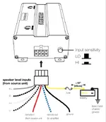
Step 3: Slide heat shrink over all the wires on the Kicker Keyloc harness, making sure to use red/black heat shrink for positive and negative wires accordingly. Once you've got your heat shrink slid on, start by grabbing 6 female insulated spade connectors and crimp them onto the bare wire ends for R+ , R- , L+ , L- , Remote In, and Remote Out. Grab your add a fuse and use a butt splice connector to connect it to the yellow power wire, and on the other bare wire end slide on heat shrink and crimp on a fork terminal. Crimp a fork terminal onto the end of the black ground wire. Once you're done with crimping/wiring the Kicker Keyloc harness, it should look like this (minus the heat shrink):

Step 4: Cut your ABS/HDPE plastic to the shape for your amp rack. I like to test fit shapes by first using cardboard and then trace them onto my ABS/HDPE before cutting that with a jigsaw. A simple rectangle will suffice but you can certainly get fancy with it. I ended up cutting/removing some of the styrofoam around the spare tire and making the shape below. This is looking into the trunk/amp rack on the right. I drilled 4 holes, inserted rivnuts, and attached my amp rack using hex head bolts at the marked spots in the pic below. The amp rack is secure and has room for a larger amp diagonally. If you we're just using the Kicker Key mono amp a smaller rack would suffice. Pic of my amp rack (ignore the wiring mess this was taken during testing phase):

Step 5: After test fitting your amp rack, remove it and start laying out your amp and Kicker Keyloc. The location of your chosen amps power/ground/inputs/outputs will determine your own orientation. You can see above where I chose to put my distribution blocks, where my power and ground come in (driver side of vehicle) and where your input wires from the factory amp will come in on the passenger side. Once you've settled on a layout, attach your gear. I primarily drill two holes at each zip tie point, run my zip ties from the back and then snip them off to make them look tidy. Once you've got everything attached to your amp rack, you can start making connections.
5.1: Run your RCA from the Kicker Keyloc to your amps input. Connect your inline fuse coming off the Kicker Keyloc to one side of your positive distribution block, and run a power wire from the other side of the distribution block to your amps + terminal. Do the same for your negative connections, ground wire from Kicker Keyloc to ground distribution block and ground wire from amp to distribution block. Make a ~1 foot remote wire jumper with an insulated male spade terminal on one end and a fork terminal on the other end. Connect the male spade terminal to the female spade terminal of the remote out on the Kicker Keyloc and then insert the fork terminal into the remote in on your amp and tighten down.
5.2: Once you've made all the connections you can with the amp rack out of the vehicle, it's time for the final install. Install your pre-wired amp rack into the vehicle and make your final connections. Match up your newly ran ~8' pigtail wires to their appropriate counterparts on the Kicker Keyloc. If you already crimped on the male insulated spade connectors to these wires, just match them up and slide them together, otherwise cut your wires to length, crimp the male terminals on and make your connections. Attach your power and ground wires to your distribution blocks. Strip back, slide heat shrink on, and crimp on a male insulated spade terminal on the remote wire coming from your cabin fuse panel. Connect the remote wire from your fuse panel to the Remote In on the Kicker Keyloc. Make a length of speaker wire to go from your Amp Output to your sub box. Connect your subwoofer(s).
Step 6: Reconnect your battery negative and start the car. Open up the Kicker test tones pages here on your phone: KICKER | Test Tones Click on the appropriate page, i.e. Keyloc or Key 500.1, and then follow the instructions for the Keyloc or 500.1 to play test tones and set your gain etc. The setup process takes maybe 10 minutes or so. Once done, enjoy your new sub(s) Here's a final shot of the trunk during testing and a close up of the trapezoidal box I made to fit behind the wheel well.


Wiring harnesses $34.99: you only need one of the harnesses (Black 16-pin) but if doing a broader install the others might be needed. The green 16-pin and black 16 pin connectors both fit the factory Bose amp but I didn't verify the other harness, will detail pin outs below:
PAC APH-GM02 AmpPro Speaker Connection Harness
Connect a new amp to your vehicle's speaker wiring in select 2014-up GM vehicles with factory Bose amp
www.crutchfield.com
Kicker Keyloc $124.99: I used the Kicker Key 2 channel LOC in conjunction with an amp I already had. If you wanted to kill two birds with one stone, you could get the Kicker Key mono amp. The 2 channel LOC can be found here:
Kicker 47KEYLOC Smart Line Output Converter
2-channel LOC with automatic tuning DSP
www.crutchfield.com
JL Audio JD 250/1 $229.99: I already had this amp from a previous install. Amp/Sub choice are personal preference. JD 250/1 here:
JL Audio JD250/1
JD Series mono subwoofer amplifier — 250 watts RMS x 1 at 2 ohms
www.crutchfield.com
JL Audio 6w3v3 $299.99: Already had this sub from a previous install. Again, amp/sub combo are personal preference. These little 6.5" JL subs put out A TON of fairly accurate bass for their size. I used this because it fit perfectly in the wheel well. Sub here:
Sub Grill $34.99: self explanatory, here:
Amp wiring kit $64.99: I usually build my own wiring from scratch, but if buying a kit Knu Conceptz is my go to. Welding wire companies like Temco Industrial are usually the cheapest. Any oxygen free copper kit will do. Won't get into wiring gauge but generally a 4 gauge kit is a happy medium. Knu Conceptz 4 Gauge OFC kit here:
4 Gauge OFC Subwoofer Amplifier Installation Kit
Buy Kolossus 4 Gauge 2 Channel Car Audio Amplifier Installation Wiring Kit made from Tinned Oxygen Free Copper. Available in Blue, Red, Green or Purple PVC .
www.knukonceptz.com
Short RCA interconnect cable $7: You could use the included one in a kit, but you only need 1-2 feet of length. 1 foot cable here:
Distribution Blocks $7: Not totally necessary. If using a Kicker Key mono amp, or if you were to do jumpers off the amp terminal for power and ground to the LOC you could skip these, just make sure you have an inline fuse before the LOC in addition to the main power wire fuse. I used a couple cheap ones like these:
Wire Ferrules $10: A mix of small and large ones is nice to have for your power/ground wires and your speaker output wires:
Flush Cutter $10: I absolutely love these for cutting zip ties:
https://www.harborfreight.com/5-in-precision-flush-cutter-57794.html
In line fuse $7: Again, only need this if using a separate Kicker Keyloc and amp. If using the Kicker Key mono amp you can skip these. The Keyloc calls for a 2 amp in line fuse:
Speaker Wire: Any old speaker wire will do, roughly 18 gauge.
Tesa Tape $8: Must have for wiring imo:
https://www.amazon.com (commissions earned)
Add a circuit $7: This is not necessary, but I prefer doing add a circuits for remote turn on. Most amps/gear nowadays have some form of signal sense/auto turn on, but I prefer to run a dedicated line. Could also tap a wire on the harnesses for remote turn on. I believe the fuse box in the cabin uses low profile mini fuses, but I had to use a regular profile mini add a circuit to make it fit correctly, like this:
Wire connectors/terminals $26 kit, insulated spade terminals $10: Mainly just need some butt splice connectors, some fork terminals, and some spade connectors. A kit like this has them all, only thing I prefer outside this kit is insulated spade connectors. Links here:
Wire Crimpers $20: Harbor freight has a nice pair here:
Wire Strippers $10: Any kind will do, some folks prefer ratcheting etc. Again HF has decent cheap ones:
Wire lug crimper $17: Super nice to have around for making your own power/ground wires.
Heat Shrink Tubing with Adhesive $16: I prefer the kind that's adhesive lined, but any will do:
Zip ties $4: https://www.amazon.com (commissions earned)
Wire loom: either braided or plastic split loom. Harbor Freight has cheap plastic split loom, or Amazon has rolls of braided wire protector. Not necessary, just makes for a cleaner install imo.
Amazon braided loom $15: https://www.amazon.com (commissions earned)
HF split loom $2: https://www.harborfreight.com/elect...-inch-x-10-ft-protective-wire-wrap-66987.html
Amp rack ABS or HDPE: Plenty of options, need enough to fit your amp/wiring so measure before hand. Plenty of options on Amazon or you can even using a plastic cutting board. Any plastic about 1/4" thick will suffice and roughly 2'x2' to cut to shape.
Rivet nut tool, rivet nuts, and bolts: I have an Astro Pneumatic one. Harbor Freight has a $50 kit that includes some rivet nuts. Grab a few bolts from a hardware store and you're set. Link to HF Rivnut tool here:
Drill/drill bits/driver bits: Self explanatory. Any drill and a set of small bits/drivers will do. Just need it to attach things to the amp rack.
I may have forgotten stuff but this should be mostly everything. A lot of this stuff you may already have on hand. Moving on to the install. I'll try and be as informative/concise as possible, again keeping in mind I won't go into too much detail on running power/ground etc.
Step 1: Disconnect your battery. Leave it disconnected while plugging/unplugging anything. You'll need it connected to move your passenger seat to remove the amp cover. Run your power, ground and remote wire. Removing the rear seat bottom there are plenty of spots to ground to. I made a little fuse holder for the engine bay like this:
Step 2: Prepare your integration wiring harness. This will avoid cutting/splicing any factory wiring. Using the wiring harness linked above, you're going to want to grab the black 16-pin harness that looks like this:
After removing the amp cover under the passenger seat, you'll end up disconnecting the same black 16-pin plug from the factory Bose amp. It looks like this (ignore the disconnected green plug/leave that connected):
Ignore the wiring labels that come on the harnesses. With the plug disconnected if you are looking straight on at the Bose amps female port/slot, the pin outs look like this:
On the PAC harness above with all the brown wires, you'll end up connecting crimping together the grey and grey/black stripe wires, and then for the other 3 channels you'll cut them in the middle, and add ~8 foot wire pig tails onto them. Do the wires one at a time and label them as you go if it helps. Make sure you are working on the male end of the plugs below, not the female end otherwise the wires will be reversed and it won't work correctly.
2.1: Start by crimping a butt connector onto one end of the grey/black stripe wire, slide your heat shrink on, and then crimp the other end of the grey/black stripe wire into the butt connector. This pin is not actually used so you could skip this but doesn't hurt to connect it.
2.2: Next, grab ~8 feet of speaker wire and strip the ends. Grab one end of the solid grey wire (Rear Left Door Speaker - ) and twist a bare wire end from your 8' speaker wire to it, make sure you keep straight which are you positives and which are your negative wires for later on. Insert both/2 wires into one end of a butt connector and crimp them in place. Slide heat shrink over, and then insert the other single grey wire into the other end of the butt connector and crimp it down.
2.3-2.5: Do these one at a time working from right to left. Your Rear Left Door Speaker - is already done (solid grey wire). Cut the Rear Left Door Speaker + wire in the middle and strip both ends. Now take the other bare wire end from step 2.2 and again, twist it to one of the brown bare wire ends, insert into a butt splice and crimp them down. Slide on your heat shrink, and then slide in the other brown wire end and crimp it down. Repeat this process for the Rear Right Door Speaker - and Rear Right Door Speaker +.
After completing steps 2.1-2.5, you should end up with connections that look like this (minus the heat shrink) Label the far end of these wires so you know which is Rear Left + and - and which is Rear Right + and -.
Your solid grey wire and your brown wires will each have a pigtail coming off of them that you'll later route back to the trunk for input at your Kicker Keyloc or Kicker Key mono amp. Wrap everything in Tesa tape to keep it compact/tidy it up. Plug the male end of your new harness into the factory amp, and plug the factory male plug into the female plug on your new harness. You can do this next step now or after you run these wires to the trunk. If you do it now you'll likely have some extra wire to coil up. If you run the wires first you can get a more precise length. Either way is okay. Slide heat shrink over the far bare wire ends and crimp on insulated spade terminals. I do all male terminals on these wires to keep things uniform. Now is also a good time to loom your wires. This step is optional, but I prefer to do it. Once your wires are loomed, you're ready to move on.
Step 3: Slide heat shrink over all the wires on the Kicker Keyloc harness, making sure to use red/black heat shrink for positive and negative wires accordingly. Once you've got your heat shrink slid on, start by grabbing 6 female insulated spade connectors and crimp them onto the bare wire ends for R+ , R- , L+ , L- , Remote In, and Remote Out. Grab your add a fuse and use a butt splice connector to connect it to the yellow power wire, and on the other bare wire end slide on heat shrink and crimp on a fork terminal. Crimp a fork terminal onto the end of the black ground wire. Once you're done with crimping/wiring the Kicker Keyloc harness, it should look like this (minus the heat shrink):
Step 4: Cut your ABS/HDPE plastic to the shape for your amp rack. I like to test fit shapes by first using cardboard and then trace them onto my ABS/HDPE before cutting that with a jigsaw. A simple rectangle will suffice but you can certainly get fancy with it. I ended up cutting/removing some of the styrofoam around the spare tire and making the shape below. This is looking into the trunk/amp rack on the right. I drilled 4 holes, inserted rivnuts, and attached my amp rack using hex head bolts at the marked spots in the pic below. The amp rack is secure and has room for a larger amp diagonally. If you we're just using the Kicker Key mono amp a smaller rack would suffice. Pic of my amp rack (ignore the wiring mess this was taken during testing phase):
Step 5: After test fitting your amp rack, remove it and start laying out your amp and Kicker Keyloc. The location of your chosen amps power/ground/inputs/outputs will determine your own orientation. You can see above where I chose to put my distribution blocks, where my power and ground come in (driver side of vehicle) and where your input wires from the factory amp will come in on the passenger side. Once you've settled on a layout, attach your gear. I primarily drill two holes at each zip tie point, run my zip ties from the back and then snip them off to make them look tidy. Once you've got everything attached to your amp rack, you can start making connections.
5.1: Run your RCA from the Kicker Keyloc to your amps input. Connect your inline fuse coming off the Kicker Keyloc to one side of your positive distribution block, and run a power wire from the other side of the distribution block to your amps + terminal. Do the same for your negative connections, ground wire from Kicker Keyloc to ground distribution block and ground wire from amp to distribution block. Make a ~1 foot remote wire jumper with an insulated male spade terminal on one end and a fork terminal on the other end. Connect the male spade terminal to the female spade terminal of the remote out on the Kicker Keyloc and then insert the fork terminal into the remote in on your amp and tighten down.
5.2: Once you've made all the connections you can with the amp rack out of the vehicle, it's time for the final install. Install your pre-wired amp rack into the vehicle and make your final connections. Match up your newly ran ~8' pigtail wires to their appropriate counterparts on the Kicker Keyloc. If you already crimped on the male insulated spade connectors to these wires, just match them up and slide them together, otherwise cut your wires to length, crimp the male terminals on and make your connections. Attach your power and ground wires to your distribution blocks. Strip back, slide heat shrink on, and crimp on a male insulated spade terminal on the remote wire coming from your cabin fuse panel. Connect the remote wire from your fuse panel to the Remote In on the Kicker Keyloc. Make a length of speaker wire to go from your Amp Output to your sub box. Connect your subwoofer(s).
Step 6: Reconnect your battery negative and start the car. Open up the Kicker test tones pages here on your phone: KICKER | Test Tones Click on the appropriate page, i.e. Keyloc or Key 500.1, and then follow the instructions for the Keyloc or 500.1 to play test tones and set your gain etc. The setup process takes maybe 10 minutes or so. Once done, enjoy your new sub(s) Here's a final shot of the trunk during testing and a close up of the trapezoidal box I made to fit behind the wheel well.