
You are using an out of date browser. It may not display this or other websites correctly.
You should upgrade or use an alternative browser.
You should upgrade or use an alternative browser.
How To: DIY Ground Wire Kit
- Thread starter Gro Harlem
- Start date
twilightprotege
Member
- :
- 2001 323 Astina SP20 (P5)
yep it dont work because protegenetwork.org is no more
i anyone needs some custom grounding ideas i have some pics in my folder.
http://www.imagestation.com/album/?id=4289591723
http://www.imagestation.com/album/?id=4289591723
I don't know them off hand, but your best bet is to find out where you want to ground them. From one point, then trace it to the next with measuring tape. Continue until you get the amount that you desire. The car in the HOW TO is an older model (2nd Gen maybe) Protege, so you don't want to come up short.
twilightprotege
Member
- :
- 2001 323 Astina SP20 (P5)
what misterT is exactly what i did....except i used string and then measured the string
Hey Mazdacub, Nice photo collection.
What are those spacers you installed? They widened your wheels somewhat? Is this a safe thing to do?
I have never heard of it before but I certainly like the look.
What's involved and what do you need to buy? If you want to start a new thread "showing them off" I have some questions and I'd rather not steal this thread.
Thanks
Robin Smith
my local protege club had a ground wire install meet today. here are the instructions.
copied and pasted from a post by niv, one of our members on mpsport.net:
Ground wire Install:
Kit:
1 - 8mm x 20mm bolt
1 - 8mm washer
1 8mm lock washer
12 feet of 4 gauge wire
10 - 4 gauge terminals (to a 10mm bolt hole)
2 4 gauge terminals (to a 5/16 (8mm) bolt hole)
1 4 gauge terminal (to whatever bolt fits a 17mm nut)*if you do the
optional right side of engine ground
1 battery terminal (11-3501-4 $3.42 w/tax @ Canadian Tire)
20 of heat shrink tube
zap straps (to make it nice and neat)
Tools:
Razor blade (box cutter)
Wire Crimper
Wire Snippers
Ratchet set (well you only need the 10mm, 13mm, 17mm and an extension)
Wrench
Heat gun (sure you could use your g/f or wifes hair dryer, but do you want to
suffer the wrath when youve wrecked it?) maybe the stove-top element
would work. I dunno.
Scissors
How To:
1. Cut wire to needed lengths - youll need 6 lengths. (these add up to 11 ,
so if you want to put that extra on one of them Id do it on #4 or #5 wire.)
a. 1 = 22
b. 2 = 7
c. 3 = 23
d. 4 = 33
e. 5 = 35
f. 6 = 20
2. You can use the terminal to decide how much wire to strip off the end of
each length. (I did one and it was just a bit more than a inch)
3. Crimp your 10mm 4gauge terminals to one end of the lengths.
4. Lay out the wires like where they are going to live when you are done, and
attach the Point As - the this step is optional but itll make your life easier
when you have to put them in for real .
5. Youll have to cut the factory wires from the terminal ring and put a new
10mm 4 gauge terminal on. (its the black wire with the yellow stripe that
disappears under the battery. Cut this as close as you can to the terminal
ring as youll need all the wire you can get)
6. Once your wire is lying the way you want, add the rest of the 10mm 4gauge
terminals to the remaining wires except for # 1,4, (5/16th) and 6 (17mm).
Make sure the terminal is lying the way you want as well, then crimp.
7. Put the 5/16th terminals on #1 and #4. and the big one on #6
8. Cut shrink wrap to 1 lengths and place over terminals and wire. Now is the
time to use that heat gun!
9. Put the new battery terminal on. (I dont know if it matters which way you
orient it, but if the terminal attachment point side is toward the left strut
youll probably have an easier time attaching #2 wire.
10. Attach the rest of the B points now.
11. For #6 B point if you remove the bolt holding the power steering fluid
reservoir, youll be able to get at the bolt for #6B easier.
12. Zap strap the wires into place, all nice and pretty.
Note* I didnt have an alarm on the car at the time of the install, and you are disconnecting the battery so you will reset your ecu and have to reset all your radio stations, as for the alarm I dont know what youll have to do. Turn it off when it starts beeping I suppose.


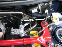
sorry for the ultra-big picture but it'll help those who are lost.
result?:
idle rpms down and gas mileage up! butt dyno tells no tales.
EDIT: 5/16th bolts, washers, lock washers should be 8mm.
copied and pasted from a post by niv, one of our members on mpsport.net:
Ground wire Install:
Kit:
1 - 8mm x 20mm bolt
1 - 8mm washer
1 8mm lock washer
12 feet of 4 gauge wire
10 - 4 gauge terminals (to a 10mm bolt hole)
2 4 gauge terminals (to a 5/16 (8mm) bolt hole)
1 4 gauge terminal (to whatever bolt fits a 17mm nut)*if you do the
optional right side of engine ground
1 battery terminal (11-3501-4 $3.42 w/tax @ Canadian Tire)
20 of heat shrink tube
zap straps (to make it nice and neat)
Tools:
Razor blade (box cutter)
Wire Crimper
Wire Snippers
Ratchet set (well you only need the 10mm, 13mm, 17mm and an extension)
Wrench
Heat gun (sure you could use your g/f or wifes hair dryer, but do you want to
suffer the wrath when youve wrecked it?) maybe the stove-top element
would work. I dunno.
Scissors
How To:
1. Cut wire to needed lengths - youll need 6 lengths. (these add up to 11 ,
so if you want to put that extra on one of them Id do it on #4 or #5 wire.)
a. 1 = 22
b. 2 = 7
c. 3 = 23
d. 4 = 33
e. 5 = 35
f. 6 = 20
2. You can use the terminal to decide how much wire to strip off the end of
each length. (I did one and it was just a bit more than a inch)
3. Crimp your 10mm 4gauge terminals to one end of the lengths.
4. Lay out the wires like where they are going to live when you are done, and
attach the Point As - the this step is optional but itll make your life easier
when you have to put them in for real .
5. Youll have to cut the factory wires from the terminal ring and put a new
10mm 4 gauge terminal on. (its the black wire with the yellow stripe that
disappears under the battery. Cut this as close as you can to the terminal
ring as youll need all the wire you can get)
6. Once your wire is lying the way you want, add the rest of the 10mm 4gauge
terminals to the remaining wires except for # 1,4, (5/16th) and 6 (17mm).
Make sure the terminal is lying the way you want as well, then crimp.
7. Put the 5/16th terminals on #1 and #4. and the big one on #6
8. Cut shrink wrap to 1 lengths and place over terminals and wire. Now is the
time to use that heat gun!
9. Put the new battery terminal on. (I dont know if it matters which way you
orient it, but if the terminal attachment point side is toward the left strut
youll probably have an easier time attaching #2 wire.
10. Attach the rest of the B points now.
11. For #6 B point if you remove the bolt holding the power steering fluid
reservoir, youll be able to get at the bolt for #6B easier.
12. Zap strap the wires into place, all nice and pretty.
Note* I didnt have an alarm on the car at the time of the install, and you are disconnecting the battery so you will reset your ecu and have to reset all your radio stations, as for the alarm I dont know what youll have to do. Turn it off when it starts beeping I suppose.
sorry for the ultra-big picture but it'll help those who are lost.
result?:
idle rpms down and gas mileage up!
butt dyno tells no tales. EDIT: 5/16th bolts, washers, lock washers should be 8mm.
Last edited:
p5sundevil said:hey this kit would work right? I wnated blue and this is an HKS style kit with the circle main plate that supposedly helps a little. Anyway it is 27 plus 11 shipping on ebay so 38 aint bad for a kit.
Of course I might be able to make it myself cheaper at home depot but the time it would take to find all the parts is worht the extra.

i bought that kit. no instructions. how the hell does the whole circle earth thing work? i was just going to run it like everyone else. anyone have any instructions on where that circle thing goes?
1Canuck2 said:Where's 5B? Same spot as 6A I assume, but just checking...
lol.. thanks for that question.. i forgot to put that in. now added in eye-sore magenta!!!
")
they aren't the same site.. and now you'll see
sorry bout that....

Attachments

So wait now Niv, aren't you missing a wire? Don't you need one from 5B to 6A? I am confused. I thought the whole point was to bring things back to the stock ground location. How does wire 6 get back there.
In your previous wires, one end of each cable joins to another, right?
1A and 4A on same bolt
5A and 3A on same bolt
3B, 4B and 2A (on neg battery terminal)
But things go from 5A to 5B and end. Then 6A and 6B are off in no mans land. Poor wire 6, no friends and no "real" grounding
Correct me if I am wrong (which is highly likely).
I am ready to pull the trigger on doing this, I have located 4 gauge red amp wire for $1.50/foot (Canadian, like $1.10 US) and am just looking for cheaper ring terminals ($3.50/pair for gold-plated - that's ~$2.50 US).
Niv, your photo is the best I have seen so far, thanks for the effort, I just want to make sure I get it right.
Thanks
Hey Robin,
I should point out first that i'm not the expert on this.. just one of the guys at the install meet who took some pics and remembered the process.
no wire is missing now with the updated picture. i didn't show 5b ending.. now it is...
wire 6 is a replacement of a existing factory wire (as you probably have noticed on your own engine), and provides a stock engine & grounding point.
I'm not too familiar with the precise electrics of this theory. But it shouldn't matter if you don't go to a stock location on 5 or 1 as you are merely providing a point of good grounding as opposed to looking for some kind of grounding circuit. As you'll notice attachment point 3A and 5A isn't a stock point.
I think as long as you are providing a route from engine to a reasonable ground point 5B not being stock is ok.
 thanks for the compliment on the photo. just wanted to make it easier for others to be able to do the same mod.
pm me with an email addy, the guy who set up our meet had already put together the kits with the ring terminals.... he might be able to give you some info on where to find it...
I should point out first that i'm not the expert on this.. just one of the guys at the install meet who took some pics and remembered the process.
no wire is missing now with the updated picture. i didn't show 5b ending.. now it is...
wire 6 is a replacement of a existing factory wire (as you probably have noticed on your own engine), and provides a stock engine & grounding point.
I'm not too familiar with the precise electrics of this theory. But it shouldn't matter if you don't go to a stock location on 5 or 1 as you are merely providing a point of good grounding as opposed to looking for some kind of grounding circuit. As you'll notice attachment point 3A and 5A isn't a stock point.
I think as long as you are providing a route from engine to a reasonable ground point 5B not being stock is ok.
thanks for the compliment on the photo. just wanted to make it easier for others to be able to do the same mod.pm me with an email addy, the guy who set up our meet had already put together the kits with the ring terminals.... he might be able to give you some info on where to find it...
1Canuck2 said:So wait now Niv, aren't you missing a wire? Don't you need one from 5B to 6A? I am confused. I thought the whole point was to bring things back to the stock ground location. How does wire 6 get back there.
In your previous wires, one end of each cable joins to another, right?
1A and 4A on same bolt
5A and 3A on same bolt
3B, 4B and 2A (on neg battery terminal)
But things go from 5A to 5B and end. Then 6A and 6B are off in no mans land. Poor wire 6, no friends and no "real" grounding
thanks
jcywong said:what is pint 6B is it just a body earth?
6B is a stock grounding point. yes, right on the body. same for 1B,2B, and 5B.
New Posts and Comments
- Replies
- 3
- Views
- 525
