NCoppersmith
Member
- :
- Mazdaspeed Protege 3.5
Anyone got the page number of the install guide? 30 minutes of flipping through pages and I still can't find it.

Tools Needed:
Ratchet
Swivel extension
3" extension
10, 12, 14 mm sockets
12mm gearwrench
Large flathead screwdriver (EGR manis only)
Channel lock pliers (EGR manis only)
Power drill with x/x bit (?)
Hacksaw
Loctite
RTV
Teflon tape
Other Parts Needed:
New gaskets
2.5" 45* silicone coupler with t-bolts
Stock manifold hardware/odds&ends
Everything else is included with your new manifold, including all washers, fittings, hoses, etc.
1. Remove Your Stock Manifold
Rather than reinvent the wheel here for the stock manifold removal, please see post #16 in the following thread for that:
http://www.mazdas247.com/forum/showthread.php?t=123615890
Placing CLEAN rags in each head port to keep out any and all debris while we work is a good idea.
Also, go ahead and remove the stock lower brace that was underneath the manifold. Doing this makes removing a stuck oil filter a breeze, because it opens up enough room to attack the filter with large channel locks. (alright)
Lastly, disconnecting the stock EGR hose from the stock intake manifold can be a real b****. If you are having trouble, removing the large coolant lines from the back of the waterneck area can help immensely.
2. EGR Hose
The new hose will take the same path as the stock one, so we need to get it out of there. Go ahead and remove it.
Bend the new EGR hose to the proper shape. Try to match the stock one as close as possible.
(Insert pic)
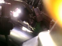
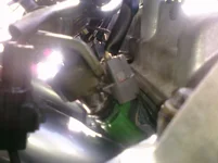
Route the new hose from the exhaust manifold area, up through the waterneck area, towards the intake manifold. This part requires EXTREME care because the hose will get very hot. I can not stress this enough. MAKE SURE that the new hose isn't touching ANY vacuum/coolant lines or wires. Use a flathead screwdriver to help bend the hose if one or more of the bends aren't clearing a line.
The pictures show some of the key points that you need to look out for, and how to route the hose. Double check this again after the new manifold is completely installed in case the hose gets moved at all.


d) Hook up the exhaust manifold side using the channel locks.
3. Fuel Rail
Mount your fuel rail / injector assembly on the new manifold. Use 2 of your stock black plastic spacers, 2 of the stock fuel rail bolts, 2 of the provided larger washers, and 2 of the provided 12mm nuts.
Do not fully tighten it down yet.
Make sure the injector tips are fully seated in their counterbores. If the hard plastic outer ring on any of the tip O-rings breaks, remove any pieces of it. The O-ring itself is fine with the hard plastic outer ring completely removed... I ran the proto with all 4 like that for almost a year. No problems. If none of them crack, which will probably be the case, even better. All depends on how brittle yours became over time in the giant oven that we all call a engine bay.

With the injectors fully seated, grab the engine flange and fuel rail in one hand. Squeeze them together while you tighten the rail mounting bolts. Snug them down enough so they will not move, but not so much that you crack the spacers. Although not completely necessary, you can loctite the nuts if you want.


Wiggle each injector and make sure they are all snug. You don't want any leaks here.

4. Throttle Body
Remove the TB studs from the stock manifold and transfer them over to the new one. Test the TB for fitment. If it is too tight for the TB to slide on, take the power drill and slightly bore out the holes on the TB itself. This is not hard to do with the x/x size drillbit, and you are barely removing any material.
The TB should slide right on now, and you can go ahead and bolt it down. Do not forget the new gasket!

5. Clean up the head surface
Pretty straightforward here. Make sure you get ANY old RTV or pieces of gasket off of the head. We need a perfectly flat and clean surface to get a good seal. Don't let any debris enter the head!
6. Mount the New Manifold (no, not that kind of mounting!) (evil)
RTV the gasket, and place it RTV-side-out on the head. Place the new intake manifold on there, holding back any and all hoses while you do it.
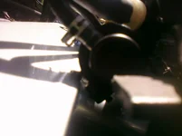
Tighten all of the mounting bolts, which are now MUCH easier to access with the new manifold. The outermost ones can be a bit tricky, so I took some pics of how I got at those. Most of the other ones are best attacked from the bottom with the gearwrench. (yes)


It is a good idea at this point to hook up the wire harnesses that have gotten disconnected.


7. Fuel Lines
Hook up the feed and return fuel lines. Nothing has changed from stock for these so you should be able to hook them up exactly reverse of how you disconnected them. The new TB position can make the routing a little tricky, but there is plenty of slack in the Perrin hose so nearly all of you shouldn't have any issues. If you are running a stock rail with stock hoses and are running into length issues, get a couple feet of fuel hose and make a new one.
8. IC Pipe
If your IC pipe makes a bend right before the TB and then utilizes a straight coupler, you will need to chop this section off with the hacksaw. Remove the pipe from the car and make the cut. Some of you higher boost guys will want to beadroll the end for peace of mind.
If your pipe uses a 90* coupler for the top bend, all you have to do is swap the 90* for the new 45* and you're all set.

9. Throttle Cable Bracket
You need to remove the 2 10mm bolts and black cable bracket from your stock manifold, and bolt it to the new one.
Use the provided small washers in a stack to shorten the upper bolt for the short hole.
Use the provided 10mm nut on the backside of the slotted hole.

Snug them both down for now, we will come back to them in the final step.
Hook up the throttle cable.


10. EGR Hose 2
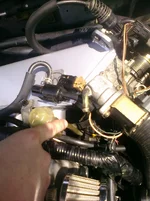
This is easiest from underneath the car, but you can also do it from the top if you have good blind feel. Hook the IM side of the EGR hose up to the fitting on the bottom of the manifold. Tighten it down fully with the channel locks.
Take your EGR valve from the stock manifold and bolt it onto the flange like in the picture. Do not forget the small metal gasket here... just reuse the one you already have.
(Insert pic)
11. Vac Lines
Take the provided brass fittings and teflon tape them. Screw them into their respective ports. Route your hoses however you like. Everyone's setup is going to be a little different here, and mine are all different from stock anyway, so I am not going to go into a ton of detail about this part. Make it as nice and neat as you can and don't forget to hook anything up.


Use the provided short rubber hose for the PCV line like shown. Trim it if needed.
(Insert pic)
12. Tuning, Adjustments, Misc.
Plug in your VICS/VTCS solenoids and ziptie them somewhere. I hooked mine up underneath the manifold and ziptied them to the runners. You are kinda limited in what you can do with them because of how short the wires are... so just tie them back securely out of view, wherever you can.
Hook up any other electronic harnesses that you haven't hooked back up yet.
Reconnect the battery.
Fire up the car and listen for leaks. If you have a leak, spray some carb cleaner in bursts, along the junctions that might be leaking. Around the TB->manifold flange, across the top of the manifold->engine flange, on the injector tips, or on the EGR block. Do this while the car is idling. You will notice a distinct change in idle when you spray the spot that is leaking.
Hopefully you are leak free without any fuss. Once you are, adjust the throttle cable tension while the car is still running. Loosen both bracket bolts, and pivot the bracket until the tension is good. Too tight and your idle RPM's will be too high. Too loose and your pedal response will have some play.
Once you find the sweetspot, snug down the slotted one first, and then loctite the shorty in place. Be gentle with it, it is just a few threads of aluminum.

Loctite the nut on the slotted one, tighten it down, and you're all set.

Lower your boost controller to it's lowest setting!
13. Go give her a rip and enjoy! (rockon)
Monitor the WOT AFR very closely with a wideband and be careful with the boost levels. Make tuning adjustments as needed and always error on the rich side. I will not be responsible for any damage to your motor that arises from improper tuning, so play it safe and be careful. The car will be breathing a lot more up top now and you will need to add fuel to compensate. The ECU will take care of it up to a point, but if you already have a freeflowing setup to start with, this manifold is going to lean it out a little up top.
Wait, when you say injector "spacers" are you referring to the injector insulators that the injector nozzle tips seat into? Please tell me you didn't remove those...
sounds like vics, vcts, and irdk.
if you're talking about VICS and VCTS (which you didn't reply to the first time I said) obviously there is nowhere for them to go.
As for vaccume, you hook up the vac lines where they fit, and connect them to the things that need vaccume.
I think you're not getting answers because the answers you're looking for are
A) obvious
B) covered in the instructions quoted earlier on this page.
Nobody else was answering, and my attempt at subtlety the first time was missed. So I went with a more direct approach. I'm sorry, its just my way!Lol, So harsh with words isnt he.
But just plug the VICS and what not back up like Rich stated and it doesnt matter how the Vac lines go as long as they are getting a source.
Can we please get pictures with outlines k thanks