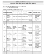
There appears to be an open circuit in the DSC/RSC system wiring. I've looked at the workshop manual but can't clearly understand the instructions shown in the attachment.
Can someone please take a look and let me know how I should go about testing for continuity?
If I want to test the continuity in LR speed sensor, should I connect one of the multimeter leads to terminal F and the other to terminal B?
To do an ohm reading on the LR ABS sensor, should I connect the leads to terminals F and I ?
Besides disconnecting the battery, any other precautions I need to take?