Need help with cruise control problem

I have an 08 mazda 3 2.3L s Touring. I'm having some issues with the cruise control that I'm hoping to get some help with.

Symptoms are:
  • Cruise control buttons all do strange things. Some times all the buttons will act like pressing the on/off button but they also sometimes just turn the cruise 'on' led on amber briefly while they're pressed and then it goes back off.
  • This started happening once in a while and then gradually got to where it is now where it rarely works
  • I have had some unintended acceleration where the vehicle will suddenly start accelerating for no reason. Tapping the brake stops the acceleration. I feel like I've only seen this happen when the cruise control is in the 'on' but not 'set' state.
What I've tried:
I initially took it to the dealer. They said they had found some codes related to the cruise control switches but they can't get the cruise control switch part any more and didn't do anything further.

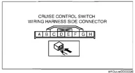
So I went home and pulled the cruise control switches and the clock spring assembly.

I took apart the cruise control switch assembly and examined the switch mechanism itself. Everything seemed in good shape and I saw no signs of wear. It looks very well built and I doubt there's issues with anything on the cruise control switch PCB.

After poking around with a multimeter for a bit I located the ground and the cruise data line. I tested first from the cruise control switch harness and then from the downstream side of the clock assembly while pressing the various cruise control buttons. Both cases resulted in a solid resistance ladder as follows:
  • No button press --> Open circuit
  • On --> 0 ohms
  • Set --> 680 ohms
  • Resume --> 2200 ohms
  • Cancel --> 120 ohms
These signals seemed stable while moving the clock spring around and wiggling it trying to induce odd values. I've come to the conclusion I don't think there's anything wrong with the switches or the clock spring. I haven't seen anything documenting what resistances I should see, but given the stability of the values I think it's unlikely something's broken here.

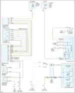
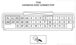
I think the next step is to check the resistances at the PCM but I'm a bit of a noob at car repair and haven't been able to find a good picture of where the pcm is (I think it's behind the battery on the driver's side at this point). More importantly I haven't been able to find a diagram for the pcm wire harness coming in so I know what wires to probe. I found a diagram that might be useful but I'm not sure if it's the right one.

So, questions:
  • First off, does it sound like I'm on the right path here?
  • Are there other issues I'm not checking that might cause a similar problem?
  • Assuming my plan is solid, does someone know where to find a pinout for the PCM so I can locate the appropriate cruise control wires?
Any other suggestions are also welcome of course :)
 
Last edited:
It absolutely sounds like you're on the right path! The PCM is located directly on the side of the battery box. There's a cover that you pop off, and then you'll see the wires and the PCM itself. Once you know what to look for, you can't miss it.

You may want to invest in a one time subscription to All Data to get the wiring diagrams and flow-chart to help with this. Getting an ELM327 adapter (a real one, not a clone!) and using ForScan may also help you out here. ForScan is a free nearly dealership level scan tool that you use on your laptop.
 
What was the code?

Whenever they say "we found a code" DEMAND a printout. Cruise is a funny thing, there are like a half dozen things that participate in it and it could be something like a faulty brake switch which might throw its own code.

Did you try and pull it with a code reader? If you do not have a reader, then I'd get one. Not sure if the cheap ones will pull this code or not as it's not directly engine related.

Also, you need a Factory Service Manual. You literally can't work on the electrical systems of cars past 2000 without one. I buy mine on ebay for like $15 for a downloadable pdf.

Here are a couple of sheets from the FSM I got off from ebay for the one cruise code I could find:

1747954306961.webp


1747954336144.webp
 
Your switch readings are spot on. So you need to verify wiring and the PCM it seems.

Also those diagrams are from an FSM for a 2007 but they should be the same for 2008.
 
Your switch readings are spot on. So you need to verify wiring and the PCM it seems.

Also those diagrams are from an FSM for a 2007 but they should be the same for 2008.
Thanks for the super useful info. I have a scanner on the way so I can check the codes myself but I didn't get them from the dealer. I'll ask next time. I'll look over all the pics you provided in the meantime. I'll be busy this weekend so I probably won't get a chance to dig into things further until Monday or so. Glad to have the pinout on the pcm connector!
 
I finally got back to doing a bit more digging here. All the above diagrams seem to indicate a cruise control signal wire entering the PCM at terminal 1AQ on the PCM connectors. However, my PCM didn't have a wire at this location. I did some further digging around and found the attached diagram.

It seems to show that the cruise control wire on a 5 speed automatic transmission actually goes to the TCM instead of the PCM. From what I understand the 2.3L engine has an independent TCM module with the 2.0L engine has the TCM integrated into the PCM.

After digging around a while I found that the 'W' on the main diagram where it goes into the TCM is the terminal/pin on the TCM connector. I also found the attached pinout for a TCM connector. I could find no indicator of what year this pinout is for, but it seemed to match mine and I could find continuity from the cruise control signal line in the vehicle to the W pin on my connector...so seems legit enough.

After pulling out my battery and disconnecting the PCM I was able to get to the TCM. I pulled the connector off of the TCM and tested resistance from pin W there to the negative battery wire. Initially everything seemed good here with the expected resistances showing up as I pressed the cruise control buttons. However, I unlocked the steering column to move it out of my way a bit and found that as soon as I could move the steering column the resistance values that showed up suddenly starting jumping around a lot. The circuit is sensitive to steering column movement for some reason. This seems to indicate some kind off wiring fault...maybe a broken wire, some corrosion somewhere...who knows.

I tested the cruise control signal wire (W on the TCM connector to A on the cruise control connector) and it was solid regardless of wiggling the steering column or not so the signal wire seems solid. I tried testing continuity from the negative battery wire to the G pin on the cruise control connector but I could find no continuity at all. If I'd seen it showing some resistance values that moved around, I'd be 100% certain this is the issue. But not being able to get any measurement is pretty strange and doesn't make sense to me:

  • G is the correct pin as specified in the troubleshooting guides provided earlier in thread
  • I empirically verified pins A and G as the correct pins where I see button resistances at the cruise control connector harness prior to it being connected
  • I was able to see the correct resistances across TCM connector pin W and negative battery wire when everything at the wheel is connected.
  • The wiring diagram that's been accurate thus far clearly shows pin G running out to ground via the brown wire to ground G5

I think my plan at this point is to try providing an auxiliary ground wire to pin G on the body side of the clock spring and see if this cleans up the issue but I figured I'd get some thoughts here first. Any clue why:

  • wiggling the steering column would cause the resistances to vary greatly?
  • I wouldn't see continuity or even a moving resistance value from pin G to ground when trying to measure it alone despite it working when connected?
 

Attachments

  • cruise-control-diagram.webp
    cruise-control-diagram.webp
    73.1 KB · Views: 5
  • TCM-pinout.webp
    TCM-pinout.webp
    17.2 KB · Views: 5
  • cruise-control-switch-harness-pinout.webp
    cruise-control-switch-harness-pinout.webp
    5.2 KB · Views: 5
Looks like that did not fix the issue. I do now have a clean signal showing the correct resistance ladder at pin W on the TCM connector. Wiggling the steering wheel no longer causes the resistances to move around, so I think I fixed part of the issue.

At this point, I believe there are three possibilities:
1) The TCM is bad
2) Wiring between TCM and PCM is bad
3) PCM is bad

I see only these two DTC's with forscan:
CodeModuleMeaning
P0564-FFPCMCruise Control Multifunction Input “A” – signal missing/invalid
B1261-FFEATCSolar Radiation Sensor Circuit Fault (in the climate control system)

Clearly the B code is not relevent here, which leaves the P code. Since the PCM is complaining, I'm assuming that cruise control information is passed from the TCM to the PCM...probably via the CAN bus. I can't really inspect that, so I have no idea what's happening here.

I suspect the cruise control signal between TCM and PCM is on the CAN bus. If this is the case, I doubt there's anything wrong with the wiring or CAN communication in general would be having issues. I think this leaves either the TCM or the PCM but I'd really like to know which before ordering expensive parts.

Any ideas on how to narrow this error down to one module here or any other suggestions on things I may have missed?
 

New Threads and Articles

Back