
You are using an out of date browser. It may not display this or other websites correctly.
You should upgrade or use an alternative browser.
You should upgrade or use an alternative browser.
Impor Tuner Article on Hyper Ground-wires
- Thread starter Gro Harlem
- Start date
BlueMP5Dave
Member
- :
- 2005 Winning Blue RX-8
I am expecting mine this week.
BlueMP5Dave
Member
- :
- 2005 Winning Blue RX-8
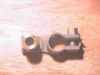
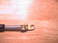
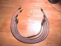
Ok here it is a inspection of kit and install report. As expected I recieved the kit on Wednesday. It was well packaged, when I opened the box I was sort of depressed in a way. It kinda looked like my amp install kit except in a box. This is a very simple kit, consisting of exactly what was in the box. Upon further inspection I found that the quality of the product was very good. All of the wires are 4AWG. The terminal ends a crimp style yet machine stamped in place. All of the terminals were solid copper. The battery post adapter is not a very impressive piece but is made of the same matierial as the battery terminal itself, I believe braised copper. Looking at the terminals that were machined in place the wires themselves are of a solid copper nature with very smal strands as advertised.
Install was a snap, no trouble at all. Instructions were clear yet left open to interuptation. Due to many options, you can connect the grounds anywhere you want really. So long as you include the left chassis ground, engine block, and right chassis ground. I will post a scan of the first page of the instructions and some pictures of the terminal ends and battery terminal. I will take further pictures of my engine tommorow. It is to dark in my garage tonight. Overall install time was about 45 minutes, once the plan for the ground positions was in place.
I spent about thirty minutes in the seat driving around. I noticed the engine has a little more torque. As for horse power there is to much ice on the ground to get a good assessment. I am pleased with the headlights, them seemed to be a little brighter. I am going to do a little more with this system. I will move the ground points around a little more and see where it takes me. As for now I am almost thinking this is a gimmick. If I can't achieve better results with further tinkering.
(edit)
I forgot to include the setup of the ground points. It is a daisy chain or series style system, You start with the right side of the engine bay and ground that to your chassis. Then from there to the throttle body. Next was the engine block ground in which you connect a extra wire off of this to your transmission. So there are three wires off of that connection. Then back to the battery post adapter. Last but not least you connect the battery post adapter to the left side chassis. This is a effective system, I believe that the throttle body ground may need to be moved to the ignition coils in order to get a better response. I will experiment some more and post again latter.
Attachments
Last edited:
BlueMP5Dave
Member
- :
- 2005 Winning Blue RX-8
BlueMP5Dave
Member
- :
- 2005 Winning Blue RX-8
jrodhotrod
Contributor
- :
- 2003 Mazda Protege5 (Mine) 2002 Nissan Sentra GXE (Wife's)
Thanks for sharing Dave! I look forward to the pictures of the install and your report on the best grounding points for the Protege5. I am really close to going ahead and ordering these myself, I am wondering if it would lessen the load that my aftermarket stereo puts on the car and help with headlight dim as you mentioned.
BlueMP5Dave
Member
- :
- 2005 Winning Blue RX-8
Man, you pointed out something else I forgot. No, help for my stereo system. I was also hoping it would keep my lights from dimming under load but it did not. My lights dimmed at the same volume levels. I am hoping that moving the points around a little bit might help if not I am back to square one.
My Stereo components: Alpine 7894 deck, Pioneer 400 watt amp runninng front and rear components, and Alpine 500 watt monno block amp running 1 JL audio 10W3 in bandpass
My Stereo components: Alpine 7894 deck, Pioneer 400 watt amp runninng front and rear components, and Alpine 500 watt monno block amp running 1 JL audio 10W3 in bandpass
jrodhotrod
Contributor
- :
- 2003 Mazda Protege5 (Mine) 2002 Nissan Sentra GXE (Wife's)
That is dissapointing. I am running something similar, just a little less power, JLAudio 300/4 and JL Audio 250/1 Monoblock. So much for the fringe benefits with these, I guess it's a "performance" mod only.
It won't do anything for the stereo. The stereo is grounding through the chassis only. SO the best things to do are keep the ground wire short, sand all grounding surfaces to bare metal, including factory. Ground the battery with the same guage as the stereos power and ground. Also run the same guage wire you used for the stereo to the alternator from the battery.
These will help the lights from dimming a bit.
Best bet is to add a 1 farad capacitor to the car. You need 1 farad of capacitance per 500 watts rms in the protege.
These will help the lights from dimming a bit.
Best bet is to add a 1 farad capacitor to the car. You need 1 farad of capacitance per 500 watts rms in the protege.
BlueMP5Dave
Member
- :
- 2005 Winning Blue RX-8
I have two 1 farad caps in my system and all they do is insure the amp is stable. It definitely does not keep my lights from dimming.
Then you need an extra battery.2001redmicadave said:I have two 1 farad caps in my system and all they do is insure the amp is stable. It definitely does not keep my lights from dimming.
HOw close are the caps the the sub amp?
Are they in line with the sub amp only or both?
Are the amps and caps grounded to the same spot?
Is the paint scraped and a proper fastener used?
What Kind of Caps are they?
Just so you know a cap can be damaged and end up being a strain on the system.
Are they in line with the sub amp only or both?
Are the amps and caps grounded to the same spot?
Is the paint scraped and a proper fastener used?
What Kind of Caps are they?
Just so you know a cap can be damaged and end up being a strain on the system.
BlueMP5Dave
Member
- :
- 2005 Winning Blue RX-8
Caps are in line with each individual amp. Ground to same position as amp. They control the voltages very well and maintain 14.4V. The problem is Alaska it is very cold where I am at (never above 10F). Except for this week, but anyways I believe that is the problem. I think the stock battery is not fully charging at full load due to being cold. I plug my car in it is winterized(battery heating pads). I have a garage it is not heated though so does some good but still does not keep car warm. I just can't wait to leave this place I only have two weeks left here and I am moving to Las Vegas. I plan on purchasing a Optima deep cycle battery soon they just want to much for the yellow tops up here due to shipping cost. My caps are made by lightning audio just standard caps with digatal read out on top. they are located no further than 10 inchs from the amps they power. I always make sure grounds have no paint to interfere and i use seat mount bolts they make excellant grounds. Thanks for all your suggestions. I have unfortunatly run out of money to spend on car audio. I have moved on to the suspesion part of this project and will be working those issues on Christmas vacation. All the parts are on order and being shipped. Now all I have to do is drive 4500 miles to Florida for vacation to get them. Cheers guys thanks for your responses.
Last edited:
BlueMP5Dave
Member
- :
- 2005 Winning Blue RX-8
Never thought of running the caps in series. I could do that thanks for the advice, I will check it out.
C
cdglowp5
Why pay 100 dollars.
Go to Home Depot or Lowes and buy the same wire and make them youreself for alot less. They will be black or off white. Will not be super pretty like those in the magzine but you still will get results.
Go to Home Depot or Lowes and buy the same wire and make them youreself for alot less. They will be black or off white. Will not be super pretty like those in the magzine but you still will get results.
BlueMP5Dave
Member
- :
- 2005 Winning Blue RX-8
Perhaps I should have said parallel. I would never do positive to negative, the cap would probally just blow a fuse though. It could possibly leak that would perhaps be another type of problem.
jrodhotrod
Contributor
- :
- 2003 Mazda Protege5 (Mine) 2002 Nissan Sentra GXE (Wife's)
2001redmicadave said:Ok here it is a inspection of kit and install report. As expected I recieved the kit on Wednesday. It was well packaged, when I opened the box I was sort of depressed in a way. It kinda looked like my amp install kit except in a box. This is a very simple kit, consisting of exactly what was in the box. Upon further inspection I found that the quality of the product was very good. All of the wires are 4AWG. The terminal ends a crimp style yet machine stamped in place. All of the terminals were solid copper. The battery post adapter is not a very impressive piece but is made of the same matierial as the battery terminal itself, I believe braised copper. Looking at the terminals that were machined in place the wires themselves are of a solid copper nature with very smal strands as advertised.
Install was a snap, no trouble at all. Instructions were clear yet left open to interuptation. Due to many options, you can connect the grounds anywhere you want really. So long as you include the left chassis ground, engine block, and right chassis ground. I will post a scan of the first page of the instructions and some pictures of the terminal ends and battery terminal. I will take further pictures of my engine tommorow. It is to dark in my garage tonight. Overall install time was about 45 minutes, once the plan for the ground positions was in place.
I spent about thirty minutes in the seat driving around. I noticed the engine has a little more torque. As for horse power there is to much ice on the ground to get a good assessment. I am pleased with the headlights, them seemed to be a little brighter. I am going to do a little more with this system. I will move the ground points around a little more and see where it takes me. As for now I am almost thinking this is a gimmick. If I can't achieve better results with further tinkering.
(edit)
I forgot to include the setup of the ground points. It is a daisy chain or series style system, You start with the right side of the engine bay and ground that to your chassis. Then from there to the throttle body. Next was the engine block ground in which you connect a extra wire off of this to your transmission. So there are three wires off of that connection. Then back to the battery post adapter. Last but not least you connect the battery post adapter to the left side chassis. This is a effective system, I believe that the throttle body ground may need to be moved to the ignition coils in order to get a better response. I will experiment some more and post again latter.
Dave, any word on further experimentation with these or pictures of them installed in your car and which grounding points worked best?
New Posts and Comments
- Replies
- 0
- Views
- 79


- Replies
- 5
- Views
- 793
- Replies
- 0
- Views
- 123
- Replies
- 27
- Views
- 2K