Here is a wiring diagram I set up for my Lancer. Instead of going to the dimmer switch I went to the cigarette lighter light bulb for the connections for the gauge bulbs. This might help clear things up for those who want a wiring diagram. My boost gauge was electric, so that's why there is a sending unit instead of just a plain vac line.

You are using an out of date browser. It may not display this or other websites correctly.
You should upgrade or use an alternative browser.
You should upgrade or use an alternative browser.
How To: Gauge Dim With Cluster Dimmer
- Thread starter MJG
- Start date
livelyjay said:Here is a wiring diagram I set up for my Lancer. Instead of going to the dimmer switch I went to the cigarette lighter light bulb for the connections for the gauge bulbs. This might help clear things up for those who want a wiring diagram. My boost gauge was electric, so that's why there is a sending unit instead of just a plain vac line.
But do they dim with the rest of the lights? That was the point of the how to.
Yes, they dim with the rest of the lights. You need to hook the gauges up to power and dimmer output. I did a search and someone said that there are three wires coming out of the MSP dimmer switch. If you hook up the gauges to the two striped wires, then you are good to go. On my Lancer, I just tapped into the two wires going into the cig lighter light, because it was connected right in with the dimmer.SNike05 said:But do they dim with the rest of the lights? That was the point of the how to.
On import cars, the dimmer switch is opposite that of domestics. The wire with the actual dimmer signal has a voltage of 1-3 volts when it's at the "brightest" setting and a voltage of 10-12 volts when at the "dimmest" setting. This is why hooking up ground and dimmer works in opposite. I haven't done any work with the MSP since I don't have mine yet, but that should give you a heads up. Once I get mine I'll borrow my friends multimeter and confirm which wires to tap into.
EDIT: And when I say POWER, I mean any lead that has 12 volts when at least the parking lights are on. Which is why accessory interior lights are the best to tap into.
mspeedP5
Contributor
- :
- '02 Protege5
yashart_mp3 said:I have an electric boost gauge though, and it says that I have to place the red wire to a +12v connection that always sees power (so that the auto zero function will work) Can I just hook this up to the battery, and hook up the black wire and white wire to my cars dimmer lights? Thanks
So did this work okay? I have an Auto Meter Electric Oil Pressure gauge.
Professor MSP
Member
- :
- 2003 Black Mica Mazdaspeed Protege
mspeedP5 said:So did this work okay? I have an Auto Meter Electric Oil Pressure gauge.
I have an Autometer electronic boost gauge. For the 12 volt constant source, I found it easier to tap in to an open spot in the fuse panel on the left-hand side of the driver's footwell. I can confirm the exact location this evening if you so wish. Other than that, follow MJG's and Leadfoot's instructions for the other wires.
This is a very nice how-to that makes all the gauges more homogeneous.
Last edited:
mspeedP5
Contributor
- :
- '02 Protege5
Professor MSP said:I can confirm the exact location this evening if you so wish.
If you could, that would be great! I'm actually in the process of installing right now...
")
Professor MSP
Member
- :
- 2003 Black Mica Mazdaspeed Protege
mspeedP5 said:If you could, that would be great! I'm actually in the process of installing right now...
Sorry, I didn't check back until now. I will post the location this evening.
Professor MSP
Member
- :
- 2003 Black Mica Mazdaspeed Protege
t3ase said:Fuse tapping is generally considered "rigging" things to work, even with a proper "fuse tap" piece. Generally, your best source is at the ignition harness.
This is the first time I have heard such a thing. Thanks for the heads-up. What specifically makes the ignition harness better than a fuse tap?
What makes this all the more interesting is that I checked my fuse tap plan with the head Mazdaspeed technican before I embarked on it. He provided the exact location for the tap, along with the tap itself, and recommended it over splicing the ignition harness. So far no problems, but maybe I am just lucky.
Professor MSP
Member
- :
- 2003 Black Mica Mazdaspeed Protege
Sorry MspeedP5, I completely spaced on getting back to you. I will try to remember to check the precise fuse tap location this evening.
Tytanium, yes, following the above instructions and using the fuse tap has worked flawlessly.
Tytanium, yes, following the above instructions and using the fuse tap has worked flawlessly.
Professor MSP
Member
- :
- 2003 Black Mica Mazdaspeed Protege
To find the fuse position for the constant 12 volt power source, open the panel to the fuse box in the driver's footwell. The configuration of the fuses is a 5 by 3 matrix (ignoring the few odd large fuses on the right-hand side of the box). The position to tap is row 4 column 1, using the (standard) convention that row 1 is the top row and column 1 is the left column.
Good luck!
Good luck!
mspeedP5
Contributor
- :
- '02 Protege5
Professor MSP said:To find the fuse position for the constant 12 volt power source, open the panel to the fuse box in the driver's footwell. The configuration of the fuses is a 5 by 3 matrix (ignoring the few odd large fuses on the right-hand side of the box). The position to tap is row 4 column 1, using the (standard) convention that row 1 is the top row and column 1 is the left column.
Good luck!
Thank-you so much! (2thumbs)
I'm going to use one of these...

Last edited:
mspeedP5
Contributor
- :
- '02 Protege5
Hmm, something strange happening. When I use the "Add-A-Circuit" I do not get any power to the gauge. If I take it out and just jam my red wire into the open slot in my fuse box, it works! Because there was no fuse in the fuse box slot, I did not put one in the replacement slot of the "Add-A-Circuit", however I did put a fuse in the second slot for the gauge.
Anyone have any ideas? I'm no electrical wiz, so this s***'s a bit of a mystery for me....
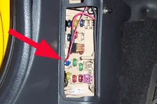
Edit: Here's a pic of where I'm tapping the fuse box for now. (Ignore the other "Add-A-Circuit". It's for my EL Sills.) I don't want to leave it like this though.
Anyone have any ideas? I'm no electrical wiz, so this s***'s a bit of a mystery for me....
Edit: Here's a pic of where I'm tapping the fuse box for now. (Ignore the other "Add-A-Circuit". It's for my EL Sills.) I don't want to leave it like this though.
Attachments
Last edited:
Professor MSP
Member
- :
- 2003 Black Mica Mazdaspeed Protege
mspeedP5 said:Hmm, something strange happening. When I use the "Add-A-Circuit" I do not get any power to the gauge. If I take it out and just jam my red wire into the open slot in my fuse box, it works! Because there was no fuse in the fuse box slot, I did not put one in the replacement slot of the "Add-A-Circuit", however I did put a fuse in the second slot for the gauge.
Anyone have any ideas? I'm no electrical wiz, so this s***'s a bit of a mystery for me....
Edit: Here's a pic of where I'm tapping the fuse box for now. (Ignore the other "Add-A-Circuit". It's for my EL Sills.) I don't want to leave it like this though.
You have tapped the correct position in the fuse matrix, so that's all fine.
The way mine is set up is that I have an in-line fuse in the fuse tap wire. Then I simply inserted the end of the in-line fuse wire in to the position you have it in. In other words, I have it set up like you have it in the picture, but with an in-line fuse in the fuse tap line.
It seems to me that you should have a fuse in the "Add-a-Circuit" if you wish to use it instead, as that would be analogous to how mine is set up.
Let me know how things go.
mspeedP5
Contributor
- :
- '02 Protege5
Professor MSP said:You have tapped the correct position in the fuse matrix, so that's all fine.
The way mine is set up is that I have an in-line fuse in the fuse tap wire. Then I simply inserted the end of the in-line fuse wire in to the position you have it in. In other words, I have it set up like you have it in the picture, but with an in-line fuse in the fuse tap line.
It seems to me that you should have a fuse in the "Add-a-Circuit" if you wish to use it instead, as that would be analogous to how mine is set up.
Let me know how things go.
I wasn't sure about putting a fuse in the empty spot since there was no fuse in the original. Does it matter what size fuse? I did have a fuse in the "extra" circuit for the gauge itself though.
The other strange thing is that when I turn off the ignition, the gauge just sits where it was. I have to turn the key back on for the gauge to "zero" itself...?
Edit: I put a fuse in the empty spot and it works okay. Still have the "zero" issue though...
Last edited:
Professor MSP
Member
- :
- 2003 Black Mica Mazdaspeed Protege
mspeedP5 said:I wasn't sure about putting a fuse in the empty spot since there was no fuse in the original. Does it matter what size fuse? I did have a fuse in the "extra" circuit for the gauge itself though.
The other strange thing is that when I turn off the ignition, the gauge just sits where it was. I have to turn the key back on for the gauge to "zero" itself...?
Edit: I put a fuse in the empty spot and it works okay. Still have the "zero" issue though...
Your gauge is working as it should be. When you turn the ignition off, the needle will remain in the position it was just prior to when you shut down. When you go to start your car again, you should turn the ignition on but not crank the engine for a few seconds. During this interval the needle on the gauge will rotate counterclockwise and read 30 inches Hg momentarily, and then rotate clockwise and come to rest at 0 inches Hg (this is the so-called auto calibration function). It is at this juncture that you may crank the engine. This process resets the zero point each time the gauge is turned on so as to compensate for operation at varying altitudes.
Good work! I really like the peak recall feature on my Autometer electronic boost/vac gauge. It saves me from having to guess what my peak boost is, and thus allows me to keep my eyes on the raod.
- :
- 2003.5 Mazda Protege' MazdaSpeed
Professor MSP said:Your gauge is working as it should be. When you turn the ignition off, the needle will remain in the position it was just prior to when you shut down. When you go to start your car again, you should turn the ignition on but not crank the engine for a few seconds. During this interval the needle on the gauge will rotate counterclockwise and read 30 inches Hg momentarily, and then rotate clockwise and come to rest at 0 inches Hg (this is the so-called auto calibration function). It is at this juncture that you may crank the engine. This process resets the zero point each time the gauge is turned on so as to compensate for operation at varying altitudes.
Good work! I really like the peak recall feature on my Autometer electronic boost/vac gauge. It saves me from having to guess what my peak boost is, and thus allows me to keep my eyes on the raod.
Guys I have the same gauge with MAP sensor.
I have no instructions and I saw that you connect the 12V source for the MAP to the fuse box. Also you guys connected the bulb power to the dimmer switch. Does this make sense?
Thanks
New Posts and Comments
- Replies
- 166
- Views
- 18K
- Replies
- 210
- Views
- 22K

- Replies
- 10K
- Views
- 3M
- Replies
- 21
- Views
- 557
- Replies
- 10
- Views
- 9K