BG (1st gen) Power Folding Mirror Technical Information

:
2001 BJFP MT
:
2016 BMYFS AT
REPOSTED FROM CLUBPROTEGE. ORIGINALLY POSTED ON 5/19/2004.


I went and pulled the complete dash harness from pseudor's GTR clip and last night BioSehnsucht and I set out to reverse engineer the mirror system.

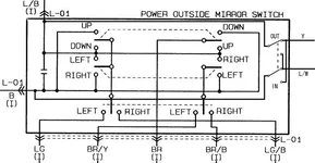
As already known, the mirror switch reverses the polarity between the L/W and Y wires, but I took it apart anyway and looked at trace pathways.

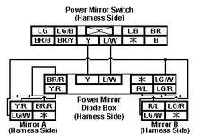
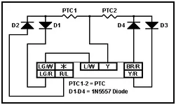
Further down the harness, those 2 wires end up at the collapisble mirror unit with 5 additional wires coming out of it. BioSehnsucht and I reverse engineered that unit and came up with a schematic that will let us build a replacement. The unit consists of 4 1N5557 diodes and 2 PTC thermistors (which we still don't know what ratings they are other than the initial 1.7 ohm state)

From that module, those 5 wires end up directly at the door harness connectors and of course it will eventually make its way to the mirrors... I don't have the complete door harnesses so there is no way I could trace it all the way.
 

Attachments

  • mirrrorswitch.webp
    mirrrorswitch.webp
    26.3 KB · Views: 296
  • protege_mirror_diagram.webp
    protege_mirror_diagram.webp
    10.2 KB · Views: 261
.
BioSehnsucht said:
In the above schematic, an additional note that the two harness connectors for the mirrors would be that the colors almost certainly will always change before reaching that connector, but thats the colors at the diode box they should attatch to those positions. When in doubt, figure out which is +, -, and switching at the mirror and wire accordingly.

Something of note is we believe that the 'fold' and 'unfold' positions of the switch (which is labelled very vaguely) were reversed when given by cablemirc, at least comparing to other mirror switches such as Nissan ones (which actually show pictures of folded and unfolded mirrors on them). We've wired the schematic accordingly (and it makes more sense this way), but if you want it to work the other way around just switch the Y and L/W wires to connect to the L/W and Y, instead of same-color, between the mirror switch and diode gizmo.
The collapsable mirror unit or whatever you want to call it, works similar to my original 2 diode idea but not quite the same.

There's two sets of 2 diodes for 4 total, one set for each mirror, and they function the same but connect to different pins (so that the always + and always - pins are seperately driven for the two sides), but share a common switching +- wire. In addition to that, there's a pair of PTC overcurrent protectors, one for each set.

If you look at the schematic you should see how simple it is.

If you wanted to make it less safe and simple you could remove the PTC's (where are just for overcurrent protection, after they overheat from overcurrent they go super high resistance and cut current until they cool off, basicly self-resetting fuses of sorts), even take out one half of it (say, D3, D4, and the pins connecting to them, now you have to split the wires elsewhere but since they get same signal anyways, no real difference other than load capacity) and you'd end up with more or less the exact circuit I designed originally.

We don't know the exact value of the PTC and weren't able to find the manufacturer based on its logo, and it doesn't have any useful markings to determine its value, but if you can determine the maximum amp rating it should carry safely and operate properly, then find a PTC that triggers at that; or just fuse them.

The diodes are a standard albeit rare type that is rather brute force, they can stand up to some crazy instantenous peak of like 1500W for 10/1000 uSec (for static discharge handling mainly, but they are quite brute force).

I have attatched the schematic of the diode box itself, the harness connector pinout is the diode box side of it, not the harness side (if you compare to the schematic above, you'll notice they're reversed in relation to each other, as that one is from the harness side).
 

Attachments

  • protege_mirror_diode_box.webp
    protege_mirror_diode_box.webp
    5.4 KB · Views: 243
.
JJB said:
for PTCs you can look at the Polyfuse line (available in DigiKey I believe) from a company called Littelfuse (see http://www.wickmanngroup.com/smarti/heinrich/producttree/searchTree.jsp?lang=en&up=true&vater=0&sohn=70&stufe=0)

On the DigiKey site:

PTC resetable fuses: http://dkc3.digikey.com/PDF/T042/0936.pdf
Bourns and Tyco also make them: http://dkc3.digikey.com/PDF/T042/1196-1201.pdf
and finally Wickman (parent company of Littelfuse): http://dkc3.digikey.com/PDF/T042/1214.pdf

Also, when using reseatable fuses keep in mind that they operate based on a thermal basis, i.e. they get hot when they are over current and that causes them to electrically open until they cool off again. This means that in the cold they will pass more current and in the hot they pass less so you want to mount these things where they are not going to get really hot. We have seen a 2:1 current swing in them from -5degC to +55degC (23-131degF) at work. Not that you are going to have a 131degF car interior, but just something to keep in mind.
 
Back