Ok, I've been trying to work this out so that the radio gets it's own battery backup that allows it to keep it's settings whenever I need to reset the ECU or disconnect the battery cable for whatever reason. It's probably ended up being more trouble than it's worth but I figured I'd post up my plans here for comments or if anyone is interested in doing the same.
Do this mod at your own risk, i assume no responsibility for your actions, etc...(blah)
Parts:
1 12v battery
1 relay(5 pin type)
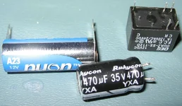
100uf, 12v electrolytic capacitor
3 wire taps
some 18AWG wire
solder
I got the relay from radio shack, and chose the smallest 12v one I could find. This relay will put a constant drain on your car battery, but it should be negligable, 30mA or about the same as a small LED.
The battery is from a battery specialty store around here called "Batteries Plus", not sure if they have those everywhere or what. (Picked up an optima red top while I was there ) When picking your battery, you should try to find one with a very good long shelf life if possible. It doesn't need to be large or anything, just capable of supplying 12v, at 3mA, and will only be doing this at times when your car's battery cable is disconnected.
So here is what to do:
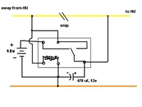
1. Assemble the parts like in the schematic. When you are done you should have a hunk of components with three wires sticking out.
2. Cover any exposed wires with your favorite insulator of choice. I wrapped mine in electrical tape.
3. Slide out your head unit and locate the wiring harness on the back. The idea is that you can install this without screwing up your radio settings, so do not remove this clip. Locate the yellow and orange wires that are right next to each other. The yellow will be positive voltage and the orange will be ground. (Note: It seems there are two ground wires, the black one also should be ground which could be used in place of the orange wire. I don't think it makes a difference.)
4. Tap into the yellow wire in two spots, and the orange in one spot. Be sure to connect the two wires to the yellow in the correct order as shown in the schematic, with one being closer to the radio than the other.
5. Once you are sure all connections are secure, clip the yellow wire in between the two tap points. Cover the two exposed ends with electrical tape to prevent shorting on the ground.
6. Now put your radio back in and enjoy never having to reprogram it. (unless of course, it locks up and you have to reset it (hand))
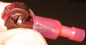
I actually made this yesterday, and wired it up, but it didn't work. Now before you go saying my design is crap, let me explain. I used t-taps to tap into the radio wire, and when I put the blade of one connector onto the tap, it got bent out of the way instead of going straight in(the third pic is an example of what I'm talking about). I didn't notice this until I had snipped the wire and tried powering up the radio. Then I basically cut up the whole thing when removing it, so I'm back to square one. I am going to try again, maybe actually using a PCB for some more stability. So yeah, the circuit is still untested at this point.
Any electronics guys please critique my poorly drawn schematic. I'm still pretty confident in this design, but maybe I had a brain fart.
The head unit draws 2.8-3mA when it is in standby. The capacitor is there to ensure the radio gets current even during the short period while the relay is switching. I don't know how fast this happens, but I calculated that 100uf would probably work fine. This is also dependant on the minimum voltage required by the head unit, which I don't know. I used a 470uf, because I just happened to have one on hand instead of a 100uf.
Do this mod at your own risk, i assume no responsibility for your actions, etc...(blah)
Parts:
1 12v battery
1 relay(5 pin type)
100uf, 12v electrolytic capacitor
3 wire taps
some 18AWG wire
solder
I got the relay from radio shack, and chose the smallest 12v one I could find. This relay will put a constant drain on your car battery, but it should be negligable, 30mA or about the same as a small LED.
The battery is from a battery specialty store around here called "Batteries Plus", not sure if they have those everywhere or what. (Picked up an optima red top while I was there
) When picking your battery, you should try to find one with a very good long shelf life if possible. It doesn't need to be large or anything, just capable of supplying 12v, at 3mA, and will only be doing this at times when your car's battery cable is disconnected.So here is what to do:
1. Assemble the parts like in the schematic. When you are done you should have a hunk of components with three wires sticking out.
2. Cover any exposed wires with your favorite insulator of choice. I wrapped mine in electrical tape.
3. Slide out your head unit and locate the wiring harness on the back. The idea is that you can install this without screwing up your radio settings, so do not remove this clip. Locate the yellow and orange wires that are right next to each other. The yellow will be positive voltage and the orange will be ground. (Note: It seems there are two ground wires, the black one also should be ground which could be used in place of the orange wire. I don't think it makes a difference.)
4. Tap into the yellow wire in two spots, and the orange in one spot. Be sure to connect the two wires to the yellow in the correct order as shown in the schematic, with one being closer to the radio than the other.
5. Once you are sure all connections are secure, clip the yellow wire in between the two tap points. Cover the two exposed ends with electrical tape to prevent shorting on the ground.
6. Now put your radio back in and enjoy never having to reprogram it. (unless of course, it locks up and you have to reset it (hand))
I actually made this yesterday, and wired it up, but it didn't work. Now before you go saying my design is crap, let me explain. I used t-taps to tap into the radio wire, and when I put the blade of one connector onto the tap, it got bent out of the way instead of going straight in(the third pic is an example of what I'm talking about). I didn't notice this until I had snipped the wire and tried powering up the radio. Then I basically cut up the whole thing when removing it, so I'm back to square one. I am going to try again, maybe actually using a PCB for some more stability. So yeah, the circuit is still untested at this point.
Any electronics guys please critique my poorly drawn schematic. I'm still pretty confident in this design, but maybe I had a brain fart.
The head unit draws 2.8-3mA when it is in standby. The capacitor is there to ensure the radio gets current even during the short period while the relay is switching. I don't know how fast this happens, but I calculated that 100uf would probably work fine. This is also dependant on the minimum voltage required by the head unit, which I don't know. I used a 470uf, because I just happened to have one on hand instead of a 100uf.