Another solution to A/C compressor problems at fan speeds 2 and 3

:
Protege5 2003
Here is my fix for the compressor failure problem in fan speeds 2 and 3. The small circuit which is installed separates the control board sense line from the fan speed control line 1, and supplies the former with a reliably low voltage when the blower is running. No modifications of the control board itself are required, although 3 wires in the harness going to it must be cut and spliced. Except for the relay you should be able to get all of the needed components at Radio Shack. In the circuit diagram the thick lines with arrows are the wires that run from the new circuit to the cut wires, and these lines are colored like the respective wires. The solid black circles are solder points. Here is a diagram of the circuit.
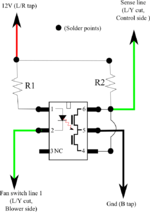
diagram1.png

The circuit works in this way. When the fan is off the wire to pin 2 floats to 12V (pulled high by the blower resistor and the blower), so there is no voltage across the LED in the solid state relay. This turns off the two FETs so no current flows through them to ground. The 10000 Ohm resistor R2 pulls the climate control sensor line high (pin 6) and the climate control unit turns off the compressor. If the fan is in postions 1,2,3, or 4 pin 2 will be at 1 to 1.5 volts, so there will be at least 10 volts between pin 2 and +12V. The 1000 Ohm resistor R1 limits the current to about 10mA. That is 5X the rated "on" for the LED, and 1/5th the maximum current. A little power will be dissipated so a 1/2W resistor is used. No significant power is dissipated in R2, so a 1/8W resistor is sufficient. With 10mA flowing through the LED the light emitted (not visible, it is inside the IC) turns on both FETs, which are wired in parallel by the jumper between pins 4 and 6 (the one bent trace). The FETs effectively short pin 6 to ground and pull the sense line to that voltage too. The climate control unit will turn the compressor on. The control unit will reliably turn on the AC because the voltage it sees is not close to its on/off threshold (as in the stock situation) but is roughly 1V
below that threshold, so it will not be confused.


Disclaimer and cautions. You do this at your own risk. If this breaks your car, too bad. You must be extremely careful while soldering inside the car. Unless you have prehensile toes or a third arm you are going to need a helper to hold the iron while you do some of the work. NEVER set the iron down in the car, even in a standard iron stand, because if it falls over it is more than hot enough to destroy any plastic it touches. Touching the seat fabric or carpet could well result in a fire. Let us not even go into the damage a hot iron can do to your person. Always wear eye protection when soldering. Unless you aspire to a case of COPD open all the car windows, or better yet, all the doors, and don't breath the smoke from the soldering. OK, you have been warned.


Parts needed:
Code:
1x Clare LCA110 solid state relay.  Digikey part number CLA101-ND $2.49 + shipping.
1x Radio Shack 278-1221, 22 Gauge solid hook up wire, 3 30ft rolls, rated 300V 80C.
1x Radio Shack 276-159, Dual printed circuit board.
1x Radio Shack 270-1801, Project Enclosure, 3" x 2" x 1"
1 foot heat shrink tubing (wide enough to hold 3 wires of the 22 Gauge, I had 
  some on hand, Radio Shack sells this too.)
1x 1,000 Ohm 1/2 watt resistor. (R1 in the diagram)
1x 10,000 Ohm 1/8 watt resistor. (R2 in the diagram)
2x zip ties (around 8")
Fine or narrow solder, with flux, "no clean".  (Note, [COLOR="red"]NOT ACID CORE![/COLOR]!!!)

Tools needed:

Philips head screw driver.
Eye protection (when soldering)
Flat file.
Small round file.
25-40W soldering iron with a small tip (conical or flat).
Something to clean the iron tip: best is a bronze "sponge" or shavings, but a 
  wad of damp paper towels will also work.
Wire stripper/cutter/screw cutter
Multimeter
Drill and bits
Extension cord
9V battery (optional)

Instructions:

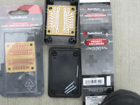
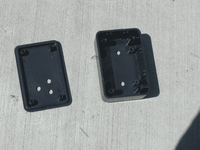
1. Open the dual printed circuit board and snap the two halves apart at the dotted line, only one will be used.

2. Open the project enclosure, set aside the metal plate (it will not be used).
board_and_box.png


3. Turn the circuit board so that the center of the IC will run up the center of the enclosure. It won't quite fit. Use the flat file to narrow the sides of the board or to remove the vertical ridges on the inside of the enclosure until it will lay flat in the bottom of the enclosure on the four small cylindrical supports there. (Don't breath the dust.) Alternatively, you could trim off the vertical plastic ridges on the enclosure with a razor blade or a chisel.

4. The holes in the circuit board do not quite line up with the holes on the supports.
Extend the holes on one end of the board inward using the small round file. A drill could also be used.

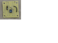
5. Place the components on the nonmetallic part of the circuit board. Bend the leads outward on the metallic side so that they stay in place while being soldered. Note the little white dot in the upper left corner of the IC is pin 1.
board_with_components_no_wires.png

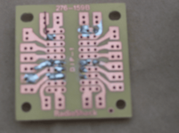
6. Flip the board over and solder the components in place as shown in the pictures. Be sure the iron is fully warmed up before soldering. Do the pins on the IC as quickly as possible - ICs do not like high temperatures. Check for solder bridges and remove any that might have formed. The black wire on the board isn't needed, just solder the long black wire in where the lower end of the black wire is. (I thought I might need to put a resistor in where the short black wire is, but in the end it wasn't needed.) Sorry about the blurry image, here is what the back of the board will look like:
back_soldered_no_wires.png

7. Cut 2 18" pieces of the green wire and 1 each 18" pieces of the red and black wire. Strip 1/4" from one end and a bit more from the other. Solder the 1/4" ends into the circuit board as shown in the diagrams and pictures.

8. Trim the excess wire and component leads on the metallic side. This is what the board will look like with the wires in place.
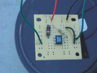
board_with_wires.png

9. Test the circuit. Attach the Red wire to the positive terminal of the 9V battery, and the Black wire to the negative terminal. Set the multimeter to measure in the lowest DC voltage range greater than 9V. For most multimeters that is most likely 20VDC. [Some multimeters apparently have a "9V" setting - that is for testing batteries, not for measuring voltage. Do not use it.] Connect it between the negative terminal of the battery and the green wire attached to pin 6. It should read 9V (whatever the battery is reading.) Touch the Green wire attached to pin 2 of the IC to the negative terminal of the battery. The voltmeter should drop to very close to zero volts.

(continued in next post)
 
Last edited:
10. Drill two 13/64" holes in the back of the enclosure, and three in the front, as shown in the pictures. Use a drill bit of the next size up to dull the edges of the holes. The hole sizes are not critical. The ones in the back are for mounting the enclosure with a zip tie, the ones in the front are to act as a strain relief. The 5 holes should also provide a little ventilation.
box_drilled.png

11. Cut two of the screws for the enclosure to about 1/4" length,as the originals are much too long to use on the short supports in the enclosure.

12. Place a zip tie through the two holes in the back of the enclosure.

13. Place the board into the enclosure and screw it into place with the two short screws. Only one end of the board will be fixed. It should be the upper end when the enclosure is mounted.

14. Bend the wires down about an inch and bunch them. Then feed them through the 3 holes (like threading a shoelace.) There should be just enough wire free inside the enclosure so that the top can be opened. Mark the green wire that goes to pin2 on the IC, so that you can tell it apart from the other green wire. A bit of tape will do.
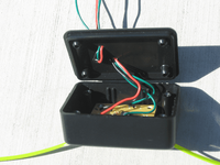
circuit_final_assembly.png

15. Screw the lid down at opposite corners with the two remaining screws.

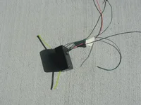
16. The assembled device is now ready to be mounted.
circuit_assembled.png


For the next several steps there are pictures in the HowTo for disabling the automatic A/C defrost modes.
http://www.mazdas247.com/forum/showthread.php?55382-How-To-Disabling-Automatic-A-C-Defrost-modes

17. Remove the glove box (squeeze the top in from the sides, then drop it down to the left).

18. Unhook the two control cables at the plastic wheels under the dash on the driver and passenger side. You will probably need to push the plastic hook on the shaft down with smooth pliers or a screw driver to free the metal loop.

19. Unhook the black clips on the control cables that are about 2-3" in from the loop ends. Careful, they have some very sharp edges.

20. Tie 5 ft. of string to each loop and tie the other end to a convenient place near that control wheel. This will let you put the cables back exactly where they were before and it is handy for guiding those cables when putting the console back together. Misroute them and the dials will hang. I was out of string and used twine - don't do that, it sheds all over the place.

21. Tilt the two center vents all the way up. Put your hands under them and pull down and out. Very little force is needed. This will partially remove the center console.

22. Detach the emergency flasher cable at the top, and the fan and control electrical cables at the bottom. Each has a lever or tab that must be squeezed to unhook the cable. If a cable won't come off with minimal force then the hook is still engaged.

23. Pull the center console all the way out slowly. Once it is clear, untie the strings from the metal loops and tie them off to the right and left, so that later you can reroute the cables with them.

24. Detach the positive lead on the battery. Turn on the headlights for a minute. Until I did this there was still 12V on the 12V wire at the climate control wiring harness, even though the battery was disconnected. (The usual advice is to detach the negative lead, and that will of course work too. There is a slight danger if the positive lead is detached and you are waving a wrench around near the battery that it might touch the positive pole and bare chassis metal at the same time, which would be really bad. That cannot happen here as we are not working near the battery.)

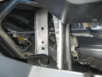
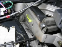
25. Mount the device in the car. It will go on the metal support with the two round holes over the one square hole. The view is from the shifter looking into the driver's side of the dash.
mounting_point.png

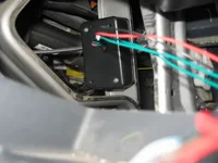
26. Push the ends of the zip ties through the round holes. The circuit board screws should be up (so that that little board is "hanging" down, even though it isn't actually that loose). Tighten the zip tie to hold it in place. The box is slightly wider than that metal support, so I angled the enclosure in so that the near edge in the photo was wedged into the corner of the channel. So far it is does not rattle. It might make sense to put a bit of spongy rubber underneath, if you have some strip insulation handy. Do not trim the zip tie yet - that way you can release and reposition it if something goes wrong. Here is what it looks like in place viewed from the shifter.
circuit_installed_from_shifter.png

(continued in next post)
 
Last edited:
27. This is what it looks like looking up from the gas pedal. In this view you can see how the enclosure extends slightly past
the side of the metal bracket.
circuit_installed_from_gas_pedal.png


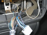
28. Time for surgery. On the control cable cut the 12V, ground, and sense wires. These are, facing into the back of the connector, the L/R wire (all the way to the left on the top), the Black wire (3rd from right on top with blanks to each side of it) and the L/Y wire (2nd from right on the bottom.) Cut them in the center of the free wire.

29. Strip all of these wires about 1/3". In the picture some of the shrink wrap is temporarily stored on the wire it will cover.
wires_cut.png


30. Tap the ground and +12V sections as shown in diagram2. In the diagram the existing wires are black, new wires are red, twisted and soldered wires are overlapping sine waves, and shrink wrap is turquoise. Twist the wires together tightly, solder them, then put a piece of shrink wrap over the conducting region and a bit of the wire insulation and shrink it by rubbing it with a clean part of the iron (one without solder on it.)
diagram2.png


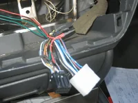
29. Clean up the wiring, pull the 4 new wires back and zip tie them to the rest of the wiring harness.
wires_spliced.png

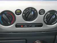
30. The moment of truth is at hand! Retrieve the center console from wherever you put it and plug in the fan and climate control electrical cables. I had to balance the console on the shift lever, an extra hand from a helper is useful at this point. Turn on the car and the AC light should stay lit when the A/C button is pressed and the fan switch is in positions 1->4.

31. If everything is working right, reassemble the center console. Reattach the emergency flasher. Pull the metal cables back into their proper positions using the strings. The one going to the right in particular tends to get jammed into odd corners, you can sort of steer it with the string while pushing the console in until it clicks. Undo the strings, put the loops back on their posts, put the black cable housings back into their clips. Again, being very careful, about sharp edges on those clips. Edit: Before attaching the wheel on the passenger side to its cable spin it to the cold setting, and be sure the dial is in that position too. Otherwise when the cable is pushed into its clamp the dial may be slightly offset, so that it won't turn all the way to cold. (Guess how I found that out!)

32. Trim off the excess zip tie on the back of the enclosure (reach up from under the dash with your head near the gas pedal.

33. Happy cooling!
circuit_success.png
 
Last edited:
With this circuit in place the compressor has now been switched on and off many tens of times over 2 days by rotating the fan dial off to 4 and back again. Because the blower contains wire coils there is the possibility that it will act as an inductor when the fan is switched between positions and the path to ground interrupted. That could result in a large negative voltage spike (that is, it could act like the points and coil on an old distributor) on fan line 1, and that could in turn blow out the LED on the input side of the IC. If this were to happen the fan would continue to work but the compressor wouldn't start in any position. So far it has not been a problem. If it is we can revisit the circuit and add some components to protect against it. I did not put these in at this point because, so far, the problem has not surfaced,
 
Last edited:
Sounds like a good project. Can you review the basic functionality of the basic OEM setup, it's weakness, and how this improves it? (or link to a previous discussion) I've only dug into things as they fail; my light is just starting to blink on intermediate positions.
 
Sounds like a good project. Can you review the basic functionality of the basic OEM setup, it's weakness, and how this improves it? (or link to a previous discussion) I've only dug into things as they fail; my light is just starting to blink on intermediate positions.

There are numerous threads on this subject, one of the longer ones is here:

http://www.mazdas247.com/forum/show...ion-To-Flickering-Fan-Speed-2-Or-3-A-C-PART-2

At post 142 in that thread (on page 10) are some voltage measurements I made. The main problem with the OEM set up is that the sense line from the climate control board turns on the compressor only when it sees <= 1.1 volts, which is measured on the L/Y wire which is connected to the fan speed 1 wire. This is a problem because in many situations on fan speeds 2 and 3 that line is actually > 1.1 volts, so no compressor. The circuit I describe shows the climate control board sense line roughly 0 volts whenever the fans are going. Since that is way below the detection threshold the climate control board works reliably.

In the long thread there are also people who report discolored or burned connectors on the fan switch. My car does not have that problem. I strongly suspect that when it does occur it indicates either a problem in the blower which results in too much current through the switch connector, or some sort of loose or dirty connector (which will could cause a large voltage drop right at the connector, with the accompanying heat).
 
OK now I see. You've figured out basically the whole deal for all of us. The compressor and light require a good ground from the switch, or the trigger wire voltage gets too high due to the resistance at the switch. So is it fair to say that the AC light & compressor are acting as indicators that the switch resistance is getting too high (i.e. the actual switch wipers and/or the connectors are loose/dirty)?

If this is true, then you are providing a means of ensuring the compressor & light will turn on OK. However, the symptom fixed here may be indicating that the switch itself will soon overheat from the local I*(V drop) and cause the familiar melted terminals - which in turn ultimately add to gross failure.

The question is whether the switch contacts wear to give a slightly elevated resistance - and stay that way - or worsen and pull a Chernobyl of their own. We might ultimately be looking for an approach like yours but essentially a 4-throw higher-current relay setup on the switch, to relieve the switch itself from its high current conditions. We need to know how typical the melting accompanies the compressor malfunction.

This also begs the question of what is the cost and availability of a brand-new switch, and its ease of installation. That might be the most practical route. Change it early before the connections are also toast.
 
Last edited:
OK now I see. You've figured out basically the whole deal for all of us. The compressor and light require a good ground from the switch, or the trigger wire voltage gets too high due to the resistance at the switch.


Possibly in some cases it is due to resistance at the switch, but not generally. The resistance on my switch was in the noise on my multimeter (too low to measure). Also when the other thread first appeared and suggested it was a switch problem I took mine apart, but there was nothing wrong with it, specifically, no pitting, burning, or heat discoloration. Also as I posted in the long thread, if you pull the console out enough to get a multimeter onto the fan switch leads, you can measure the voltage between the ground wire and the blower wires. Unless your unit has indications of excessive heat the voltage drop on all of those settings will be <0.1V. That tells you there is nothing wrong with the switch itself or the connections to it.

I think the problem is that somewhere during design Mazda put a diode in downstream from the fan switch (see my measurements in the long thread) but did not increase the trigger threshold in the climate control circuit to compensate. That put the threshold within spitting distance of the actual voltage, and bellow it under some circumstances. On my car, for instance, on cold days the A/C would always work on positions 2 and 3, it just wouldn't work on hot days when it was needed!
 
Remember how you pondered the .45V to ground in pos. 1? I attributed it to the switch. What about beefing up the ground wire from the switch to eliminate most of this drop and help the threshold issues?
Code:

Blow Wire Voltage at AC lit?
Position color Blue/Yellow
1 Blue/Yellow .45 Y
2 Blue 1.04 Y
3 Blue/Red 1.15 N
4 Blue/white .89 Y
 
Remember how you pondered the .45V to ground in pos. 1? I attributed it to the switch.

I don't, the measured resistance across the switch in my car was too low.

As for adding a thicker wire, it shouldn't be needed. Also straight resistance doesn't fit the measurements. Look at post 144 where the voltages measured at each wire (and not just at the L/Y speed 1 wire) are shown:

Code:
Switch    Wire       Voltage
Position
1           Blue/Y    .45
2           Blue      .85
3           Blue/Red  .85
4           Blue/W    .81

The current goes way up from positions 2->4, look at the wire gauges used for those lines, yet the voltage drop across the switch to ground doesn't change (much). That IV characteristic is typical of a diode, not a resistor. Also the voltage drop of around .85V is pretty typical for a forward biased large capacity diode. In other words, I think this corresponds to the Vd area of figure 5 here:

http://en.wikipedia.org/wiki/Diode

with the .45V corresponding to the "elbow" of that curve.

On the other hand...

If you did connect a new ground wire from the switch back to the negative terminal it would bypass the diode, and you should indeed see a large drop in voltage on the sense line. But you have to think that the Mazda engineers had some reason for putting that diode in, so maybe bypassing it isn't the best idea...
 
yeah if indeed there's a diode in there not on the schematic, for sure. Guess you could tear back into it and try to forward and reverse bias the switch to chassis ground while in position 0 to try and verify.
 
yeah if indeed there's a diode in there not on the schematic, for sure. Guess you could tear back into it and try to forward and reverse bias the switch to chassis ground while in position 0 to try and verify.

Putting a voltage below ground on the fan switch ground wire might not be a good idea, who knows what else might be on that ground line upstream of the diode. I suppose one could put known amounts of forward current down the fan ground line and measure the resulting voltage. If it looks like a diode characteristic, it probably is. But that isn't much different from the direct voltage measurements on lines 1->4 at the blower.

That whole wiring harness is a bit odd, since there is an electrical connection on the L/Y line between the two connectors, but wherever that splice is, it isn't near any of the connectors. All one sees are the two L/Y wires disappearing into the bundle near the climate control, and a single L/Y wire emerging from the bundle near the blower resistor. Perhaps the diode is in the same place as the 3 wire L/Y junction?
 
i dont know if this makes any sense or if would help with anything but what if you were to cut the ground wire and put both ends of the wire directly to the chassis would this do anything as far as the load is concerned
 
All I know is that I'm going to do this and if this fixes my A/C, I love you man. I made comments about this years ago, agreeing with you that its not the dang switch. For the simple reason that it works fine on heat just not on A/C. I at least gave it a shot and tried all those stupid guesses, and none of them did a damn thing. I actually took my car to dealership back in like 04 when it was still under warranty, and I wish to god I could remember what they said it was, but it was something the were gonna replace, not the whole control unit, but a component in it, something about voltage too low. Well they wouldn't do it under warranty cause my car had been totaled previously, and then charged me $80 for a diagnostic fee. Then had the balls to ask me about my turbo setup and tell me how cool my car was when I went out to drive it off.

You really should just put together your fix and sell them off, you will be the most popular person on the forum. I will paypal you right now if you would just make me one, i'm so busy now I just dont have the time. How much you want?
 
You really should just put together your fix and sell them off, you will be the most popular person on the forum. I will paypal you right now if you would just make me one, i'm so busy now I just dont have the time. How much you want?

Yes...please!!!!
 
You really should just put together your fix and sell them off, you will be the most popular person on the forum. I will paypal you right now if you would just make me one, i'm so busy now I just dont have the time. How much you want?

It isn't hard for me to make these things. If there were no lawyers and no laws I would be happy to do what you ask. However, in the real world if I were to sell them there would be all sorts of potential liability issues.

Not that I think this likely, but imagine what happens in the worst case scenario: one of my devices shorts out, catches fire, smoke fills the cabin and the driver crashes and dies. Here come the lawyers and there's no limit to the damages they can seek. Heck, the fire could start somewhere else under the dash, the post crash investigation finds my device, and it gets the blame even though it wasn't the actual cause. Plus for all I know there is some DOT regulation that this fix violates (illegal material for use in a car, for instance).

Posting here to describe the fix does not have the same liability issues - the only thing I have "sent" anybody is a description of something I did myself. Freedom of speech. If somebody else builds one and attaches it to their car then they have only themselves to blame if it somehow goes wrong. (Not that I think it would.)
 
Did anyone ever isolate what degrades over time to give us the problem (i.e. the sense line voltage grounding residual voltage too high to trigger)? I'm assuming here that most all P5s didn't do this when first delivered. If not the fan speed switch itself wearing out, is a wiring connector going bad? Blower resistors losing resistance somehow? I think most happen sort of gradually(?) Something is changing...
 
pasadena_commut,
I love what you done here, but I do have to disagree with your instructions on testing the circuit. Specifically the part in red.

"9. Test the circuit. Attach the Red wire to the positive terminal of the 9V battery, and the Black wire to the negative terminal. Place the multimeter in an appropriate voltage range between the negative terminal of the battery and the green wire attached to pin 6. It should read 9V (whatever the battery is reading.) Touch the Green wire attached to pin 2 of the IC to the negative terminal of the battery. The voltmeter should drop to very close to zero volts."

If you check the voltage of a battery but have a resistor in the circuit you will not get the battery voltage. You should get a reduced voltage reading.

-Actually test data-

*red probe on + and black probe on - of battery = 9.31v
*red probe after 1000 ohms resistor and black probe on - of battery = 4.46 v
*red probe after 10000 ohms resistor and black probe on - of battery = 0.78 v

Your directions are to hook the red probe up the the green wire going to pin 6 and black probe to - of the battery. That effectively is like checking the voltage after the 10000 ohms resistor.

The rest of your testing and the circuit works as described.


-Actually test data-

*red probe on green wire going to pin 6, black probe on - of battery, touch green pin 2 wire to negative battery terminal = 0.00v

I will be installing this beauty into my car this weekend, and keep you guys posted. I am probably going to be inspecting my connector as well because the 4th fan setting in AC has been flaky sometimes lately.


***ADDITIONAL NOTE***
In the picture of the components on the circuit board, understand that the bigger resistor (R1) may look different. R1 should be larger than R2 because it handles more wattage. My R1 is brown body and has a golden strip. The color of the resistor body, not the bands, does not matter. The last strip is usually gold or silver, with gold being more accurately to the set resistor value.
 
Last edited:
RABID_MP5,
From what I understand it appears to be the connector to the fan switch can corrode or oxide a bit over time which increases the resistance. That in turn puts the sense voltage at or eventually below the threshold voltage for circuit to activate the AC. I am sure Mazda engineers took this into consideration when designing the circuit board for the fan. The point made here is that we believe a diode was put down stream somewhere in the wiring. This was most likely a fix to a bigger problem after they came off the assembly line maybe. I am not surprised that this happened considering this car eats headlight bulbs and the only way to fix it is HID kit with a rely kit.
 
Back