Anyone have any clue as to which wires to tap into to wire LED door sills. I found a harness plug that when removed will shut of the dome lights. However, only 3 wires were hot. Each one when tapped would turn on the led door sills, but then they would not turn off. Looking for tips, hints, or descriptions as to where to wire these properly.

You are using an out of date browser. It may not display this or other websites correctly.
You should upgrade or use an alternative browser.
You should upgrade or use an alternative browser.
How to wire LED Door Sills?
- Thread starter Migkaspar
- Start date
I would like to get an answer to this as well as I am having no luck finding which wires carry power and where to ground the other LED cable.
my original post and progress - http://www.mazdas247.com/forum/showthread.php?123821418-Door-sills/page4
my original post and progress - http://www.mazdas247.com/forum/showthread.php?123821418-Door-sills/page4
HOW TO WIRE LED DOOR SILLS GUIDE with some photos Part 1
Ok, here goes my first attempt at the how to guide of how to do something. I hope this helps all those who struggled with the task that I was finally able to complete Saturday afternoon, which was of course wiring LED door sills.
Materials List/Tools
1.) LED Door Sills
2.) Phillips Screwdriver
3.) Small Flathead screwdriver
4.) 10mm socket and ratchet
5.) Pliers
6.) Quick Clip Wire taps
7.) Wire cutters (maybe)
8.) 2 small pieces of thicker wire (The LED wire was small, and I had a hard time keeping it in the quick connectors so I soldered a thick wire to the end.
9.) Printout of the wiring schematic: 3 pages (http://am.mazdaserviceinfo.com/emaz...s/SM/2013/CX5/mv/books/mvd09/html/0918_8.html)
10.) Extra 3mm double sided tape (optional, but read others who said it was helpful, I applied as much as I could).
I believe that was all that I used.
Procedure:
1/2.) Not meant to be offensive, but remember that this is a Japanese made car so things aren't done the way an American would think they would be. As in I want to wire these LED lights, I probably want to tap into a wiring harness located near the fuse panel which is on the drivers side under the steering wheel. Right? and as other have posted they connected....WRONG! This was my first attempt about a month ago, I was able to find a harness connector that when disconnected would turn off the dome lights. Even managed to find 3 hot wires in the harness that would when connected light the door sills. SCORE, however when grounded they would not turn off when the doors were closed. DANGIT. With help from the forum, I was told the the circuit was ground switched/delayed, that I need to find the dome ground wire. Easier said than done. Spent 2 more hours trying every wire in the harness....NO GO...lights remained on. So I disconnected and did more research.
Step 1.) Print the wiring schematic. Either here: http://am.mazdaserviceinfo.com/emazda/dealersystem/service/esi/en_us/SM/2013/CX5/mv/books/mvd09/html/0918_8.html
Or: Use these: (Pay attention to the red circles)


2.) Pop off the door sill plastic panels at each door. They are just snapped together and should pop out with a slight tug upwards. I decided to attach my door sills to the metal sill instead of the plastic panel. So I also lifted the rubber seal trim piece up a little and fed the wire from the led underneath, then replaced the rubber seal. Connect the longer wires to each of the led door sills and snake the wire to the BACK of the car. I was able to use the small straight screwdriver ans slide the wire underneath the plastic that was on the pillar between the front and back door. You may want to leave one of the door sills unattached but connected and laying inside so that you can test the wiring later and ensure that they do indeed turn off.
3.) Open the back hatch. I am assuming for those of you with right hand drive your back side panel will be opposite, but you need to remove this. . The back quarter panel, for me it was the side with the rear cargo light and the latches for the 40/20 seat release. (I have 40/20/40 seats). To remove this back quarter panel, you must first remove everything from the cargo area. I took out everything down to the spare tire, leaving just the spare tire in the rear. Next remove the trim piece that goes across the back tailgate and hatch clasp. There is a panel popper pin on each side. Use a small flat screwdriver to pop the center circle up and the pin will come right out. The trim piece then pops out with a tug upwards like the door sill plastics did. Next you will see and need to remove another panel popper pin that is holding the quarter panel that was underneath the trim piece you just removed. Using the flat screw driver you will need to pop open 3 covers. 1 will be located that the levers for the seat release, and the other two are the cargo hooks. The cargo hooks cover opens from the bottom and hinges up. Use the ratchet and socket to remove the two screws from the cargo hooks, and a phillips screwdriver to remove the screw from behind the seat release levers and also where the cargo cover/shade attaches. The quarter panel can now be pulled and popped off the side of the car, as there are only a couple panel poppers holding it. Watch the cargo light and seat levers are still attached. The seat levers can be twisted and sent through the hole, and you can reach behind the panel and unhook the wire connecting the cargo light.
4.) With the rear panel removed you should see a few black modules and multitudes of wires attached to the side of the car. You should find a black box, possibly with a wiring harness connector attached to it, mine did. That reads BCM rear or something to that effect. This is the RBCM that is referenced in the wiring schematics. There are two wiring harnesses that are connected to the bottom (white) and 1 blue harness connect to the left side. I removed the wiring harness that was connected to gray plug on the RBCM, as seen in the picture. You can verify if you so choose by removing each of the plugs 2 white and 1 blue one at a time from the RBCM and you will notice that 1 white and the 1 blue cause the dome lights to go out when removed, while the other white just causes it to fade when removed. You actually do not want either of these wiring harnesses as they do not match with the 0940-102A harness as circled on pages 1 and 2 of the schematic.
Ok, here goes my first attempt at the how to guide of how to do something. I hope this helps all those who struggled with the task that I was finally able to complete Saturday afternoon, which was of course wiring LED door sills.
Materials List/Tools
1.) LED Door Sills
2.) Phillips Screwdriver
3.) Small Flathead screwdriver
4.) 10mm socket and ratchet
5.) Pliers
6.) Quick Clip Wire taps
7.) Wire cutters (maybe)
8.) 2 small pieces of thicker wire (The LED wire was small, and I had a hard time keeping it in the quick connectors so I soldered a thick wire to the end.
9.) Printout of the wiring schematic: 3 pages (http://am.mazdaserviceinfo.com/emaz...s/SM/2013/CX5/mv/books/mvd09/html/0918_8.html)
10.) Extra 3mm double sided tape (optional, but read others who said it was helpful, I applied as much as I could).
I believe that was all that I used.
Procedure:
1/2.) Not meant to be offensive, but remember that this is a Japanese made car so things aren't done the way an American would think they would be. As in I want to wire these LED lights, I probably want to tap into a wiring harness located near the fuse panel which is on the drivers side under the steering wheel. Right? and as other have posted they connected....WRONG! This was my first attempt about a month ago, I was able to find a harness connector that when disconnected would turn off the dome lights. Even managed to find 3 hot wires in the harness that would when connected light the door sills. SCORE, however when grounded they would not turn off when the doors were closed. DANGIT. With help from the forum, I was told the the circuit was ground switched/delayed, that I need to find the dome ground wire. Easier said than done. Spent 2 more hours trying every wire in the harness....NO GO...lights remained on. So I disconnected and did more research.
Step 1.) Print the wiring schematic. Either here: http://am.mazdaserviceinfo.com/emazda/dealersystem/service/esi/en_us/SM/2013/CX5/mv/books/mvd09/html/0918_8.html
Or: Use these: (Pay attention to the red circles)
2.) Pop off the door sill plastic panels at each door. They are just snapped together and should pop out with a slight tug upwards. I decided to attach my door sills to the metal sill instead of the plastic panel. So I also lifted the rubber seal trim piece up a little and fed the wire from the led underneath, then replaced the rubber seal. Connect the longer wires to each of the led door sills and snake the wire to the BACK of the car. I was able to use the small straight screwdriver ans slide the wire underneath the plastic that was on the pillar between the front and back door. You may want to leave one of the door sills unattached but connected and laying inside so that you can test the wiring later and ensure that they do indeed turn off.
3.) Open the back hatch. I am assuming for those of you with right hand drive your back side panel will be opposite, but you need to remove this.
. The back quarter panel, for me it was the side with the rear cargo light and the latches for the 40/20 seat release. (I have 40/20/40 seats). To remove this back quarter panel, you must first remove everything from the cargo area. I took out everything down to the spare tire, leaving just the spare tire in the rear. Next remove the trim piece that goes across the back tailgate and hatch clasp. There is a panel popper pin on each side. Use a small flat screwdriver to pop the center circle up and the pin will come right out. The trim piece then pops out with a tug upwards like the door sill plastics did. Next you will see and need to remove another panel popper pin that is holding the quarter panel that was underneath the trim piece you just removed. Using the flat screw driver you will need to pop open 3 covers. 1 will be located that the levers for the seat release, and the other two are the cargo hooks. The cargo hooks cover opens from the bottom and hinges up. Use the ratchet and socket to remove the two screws from the cargo hooks, and a phillips screwdriver to remove the screw from behind the seat release levers and also where the cargo cover/shade attaches. The quarter panel can now be pulled and popped off the side of the car, as there are only a couple panel poppers holding it. Watch the cargo light and seat levers are still attached. The seat levers can be twisted and sent through the hole, and you can reach behind the panel and unhook the wire connecting the cargo light. 4.) With the rear panel removed you should see a few black modules and multitudes of wires attached to the side of the car.
You should find a black box, possibly with a wiring harness connector attached to it, mine did. That reads BCM rear or something to that effect. This is the RBCM that is referenced in the wiring schematics. There are two wiring harnesses that are connected to the bottom (white) and 1 blue harness connect to the left side. I removed the wiring harness that was connected to gray plug on the RBCM, as seen in the picture. You can verify if you so choose by removing each of the plugs 2 white and 1 blue one at a time from the RBCM and you will notice that 1 white and the 1 blue cause the dome lights to go out when removed, while the other white just causes it to fade when removed. You actually do not want either of these wiring harnesses as they do not match with the 0940-102A harness as circled on pages 1 and 2 of the schematic.
Last edited:
HOW TO WIRE LED DOOR SILLS GUIDE with some photos Part 2
4. Cont.) The wiring harness 0940-102A which contains the important 1E violet ground wire and the 1H Lavendar/White (Blue/white) hot wire is located above the the blue harness, as seen here: (you will also notice the blue quick connecters that I used to tie into the wires. ignore the green and black wires those were the wires that I used to attach to the LED Door sill wiring.) This white harness above will only have 3 wires. A violet, brown and blue and white. As posted in the door sills post these are the wires that tireman1 was mentioning here: post #15 http://www.mazdas247.com/forum/showthread.php?123821418-Door-sills. You need to tap into the blue and white wire for the power and to the violet wire for the ground.
5.) Zip tie the door sill wires to some of the other wiring to ensure it was out of the way. You may also want to zip tied the inline fuse that the door sills have back towards the tail lights, so that it could be easily reached via the access panel that allows for the tail light bulbs to be replaced should you ever need to replace the fuse.
6.) I left the battery connect the entire time, as I chose to listen to music while I worked. So at this point you should notice that the door sills are lit if you have a door open. You may want to do a test at this time to check that the door sills go out when all the doors are closed and the dome light times out. (This is why it was important to leave one sill unattached and laying inside.)
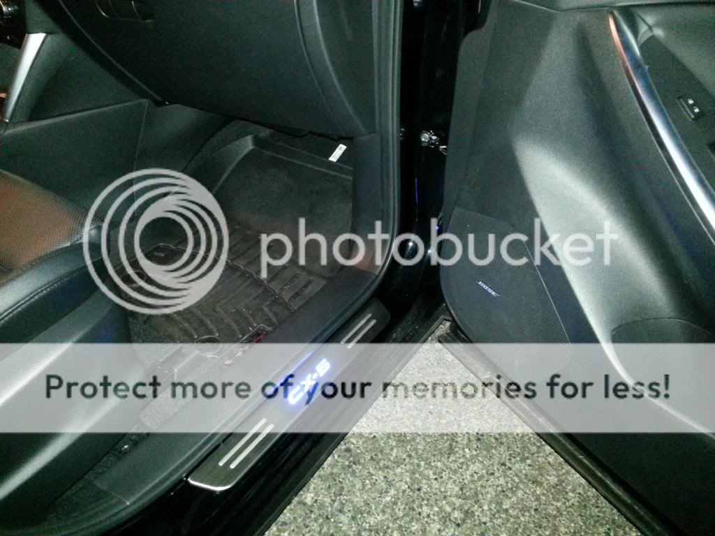
7.) Replace the panels. Starting with the front doors and working your way to the back. And that should do it. So now when you open the doors you should see this:
I hope this helps all of you who where as frustrated as I was trying to get these things all wired up. Honestly if I had to do it again, I think I could do it in about 25 minutes, instead of the hours I spent up under the steering wheel.... Should you have questions feel free to message me. I'll try to check back on the posts and address questions here.
Goodluck.
(disclaimer: I am not to be held responsible should you do damage to your vehicle.)
4. Cont.) The wiring harness 0940-102A which contains the important 1E violet ground wire and the 1H Lavendar/White (Blue/white) hot wire is located above the the blue harness, as seen here:
(you will also notice the blue quick connecters that I used to tie into the wires. ignore the green and black wires those were the wires that I used to attach to the LED Door sill wiring.) This white harness above will only have 3 wires. A violet, brown and blue and white. As posted in the door sills post these are the wires that tireman1 was mentioning here: post #15 http://www.mazdas247.com/forum/showthread.php?123821418-Door-sills. You need to tap into the blue and white wire for the power and to the violet wire for the ground. 5.) Zip tie the door sill wires to some of the other wiring to ensure it was out of the way. You may also want to zip tied the inline fuse that the door sills have back towards the tail lights, so that it could be easily reached via the access panel that allows for the tail light bulbs to be replaced should you ever need to replace the fuse.
6.) I left the battery connect the entire time, as I chose to listen to music while I worked. So at this point you should notice that the door sills are lit if you have a door open. You may want to do a test at this time to check that the door sills go out when all the doors are closed and the dome light times out. (This is why it was important to leave one sill unattached and laying inside.)
7.) Replace the panels. Starting with the front doors and working your way to the back. And that should do it. So now when you open the doors you should see this:
I hope this helps all of you who where as frustrated as I was trying to get these things all wired up. Honestly if I had to do it again, I think I could do it in about 25 minutes, instead of the hours I spent up under the steering wheel.... Should you have questions feel free to message me. I'll try to check back on the posts and address questions here.
Goodluck.
(disclaimer: I am not to be held responsible should you do damage to your vehicle.)
Addendum.... After having these installed for about a month, I had one go out. From what i can gather, somehow the plug connecter between the light and the wiring got wet. (Not going to blame my 4yr old but it was his side in the back and he has occasionally dropped his water bottles) and shorted... I would suggest putting some shrink tubing or taping those connectors. I immediately went around and taped the other ones.
Chris_Top_Her
Contributor
- :
- San Antonio, Texas
- :
- '15 CX-5 Miata AWD
You can also use a flat screwdriver to push the door catch to trick the car into thinking the door is closed when testing the lights on/off.
Just now put my car back together. Unfortunately, my LED door sills did not light. I'm fairly certain I followed the instructions correctly.
To re-iterate I spliced the red wire from the door sills to the blue/white and the black wire to the lavender.
But thanks Migkaspar for the write-up. Does anyone have any suggestions?
Thanks,
Tommy
To re-iterate I spliced the red wire from the door sills to the blue/white and the black wire to the lavender.
But thanks Migkaspar for the write-up. Does anyone have any suggestions?
Thanks,
Tommy
Thought about this some more. According to the wiring diagrams, we are supposed to connect the door sill into the same circuit as the front dome lights.
If I had screwed up the wire splicing, then the front dome lights would probably not work either. We I just checked and the dome lights are functioning properly.
This leads me to think that there is something wrong with the door sill wires.
Thoughts?
If I had screwed up the wire splicing, then the front dome lights would probably not work either. We I just checked and the dome lights are functioning properly.
This leads me to think that there is something wrong with the door sill wires.
Thoughts?
TreyP
2018 Soul Red AWD Touring CX-5
Did you check the new wires with a test light to be sure they have good connections?Thought about this some more. According to the wiring diagrams, we are supposed to connect the door sill into the same circuit as the front dome lights.
If I had screwed up the wire splicing, then the front dome lights would probably not work either. We I just checked and the dome lights are functioning properly.
This leads me to think that there is something wrong with the door sill wires.
Thoughts?
Did you check the new wires with a test light to be sure they have good connections?
I disconnected one of the door sills from the provided wire. Using a volt meter, I was not getting any current from the wire. I'll have to take apart the trunk area again to check my splices.
Still seems weird to me that the dome lights still work while the door sills aren't getting any juice.
TreyP
2018 Soul Red AWD Touring CX-5
If you press the FLOW button and observe the way the current flows in different situations by pressing Door Open and On/Off, it shows that the purple wire is only activated when the switch is in the "Door" position. The map lights would still work when they were manually turned on. I don't know if that helps or not, just an observation.
http://am.mazdaserviceinfo.com/emaz...s/SM/2013/CX5/mv/books/mvd09/html/0918_8.html
Also, I noticed you have a '14 and the OP has a '13, perhaps there was a color change in the wires for the new model. I haven't done the door sills, so I can't say for sure, but just something to consider.
http://am.mazdaserviceinfo.com/emaz...s/SM/2013/CX5/mv/books/mvd09/html/0918_8.html
Also, I noticed you have a '14 and the OP has a '13, perhaps there was a color change in the wires for the new model. I haven't done the door sills, so I can't say for sure, but just something to consider.
Last edited:
Chris_Top_Her
Contributor
- :
- San Antonio, Texas
- :
- '15 CX-5 Miata AWD
When I first had mine installed, the tech who did it utilized an electro magnetic relay. I was annoyed by the buzzing when the voltage drop dimmed the light, and eventually went back to the place. Two other techs there looked at it, and re-wired it without the relay (apparently one of the daisy chaining wires/connector was bad too). If having too much trouble take it to an audio shop (the kind that also wire back-up cameras etc).
If you press the FLOW button and observe the way the current flows in different situations by pressing Door Open and On/Off, it shows that the purple wire is only activated when the switch is in the "Door" position. The map lights would still work when they were manually turned on. I don't know if that helps or not, just an observation.
http://am.mazdaserviceinfo.com/emaz...s/SM/2013/CX5/mv/books/mvd09/html/0918_8.html
Also, I noticed you have a '14 and the OP has a '13, perhaps there was a color change in the wires for the new model. I haven't done the door sills, so I can't say for sure, but just something to consider.
Appreciate that you guys are looking into this and helping me out. So thanks!
I do realize that the switch needs to be in the DOOR position. I also tried to search for the 2014 wiring diagram, but did not find one. However, after looking at the actual wiring in my car I'm confident that the 2013 diagram still applies.
I suspect questionable installation of the quick clips on my part. I just need to find some time to tear apart my car again.
Okay, success finally!
While the OP suggests using quick clips, I just did not have confidence in the my installation of them. I'm sure they work just fine.
I just felt more confidence visually seeing that the connection was made. I opted to just solder the new connections instead of the quick clips.
I removed the clips. Soldered the sill wires onto the original wires. Taped and shrink wrapped the new connections. Doubled checked the fuse. Then finally verified current with the volt meter. The extra work paid off.
Not saying that there was an error in the OP's procedure, he provided installation that anyone should be able to do. Thanks everyone for the help.


Last edited:
Found this installation instruction on an English website:
http://shop.crayford-mazda.co.uk/product/Illuminated_Scuff_Plates_KD45-V1-370
See under the tab Related Files.
http://shop.crayford-mazda.co.uk/product/Illuminated_Scuff_Plates_KD45-V1-370
See under the tab Related Files.
2016 CX-5 update
First, thanks to Migkaspar for a great and helpful installation guide. Updates for 2016 model:
1. RBCM location is same as 2013 (Behind rear LHS quarter panel, for both RHD and LHD variants). Most Japanese cars built for global markets are built primarily for LHD, you can tell by the LH filler cap! That is, everything is the same except for steering and dash
2. Wire colours are the same. Connector appears to have an extra set of (unused) pins, but just work on the wire colours
3. Seat release latches are now fixed to the body behind the quarter panel by a steel bracket with two M10 bolts (wide flange). Pry the panel open, and remove bolts with small socket. There is an additional 'S" shaped tag on the end of the bracket the slots into a hole in the body, so the bracket must be rotated away from the body to free it. Once this is done, with all other fasteners removed, you can swing the panel away from the body without removing the latch assembly. You need to unclip a cable ring around the harness and the seat release cables to do this.
4. Cargo light now on tailgate, not quarter panel.
Cable lengths for the scuff plates mandate that the cable for the RHS plates is run under the back of the rear seats to the LHS. Take care not to foul any of the seat mechanisms.
How to wire LED Door Sills 1 & 2
First, thanks to Migkaspar for a great and helpful installation guide. Updates for 2016 model:
1. RBCM location is same as 2013 (Behind rear LHS quarter panel, for both RHD and LHD variants). Most Japanese cars built for global markets are built primarily for LHD, you can tell by the LH filler cap! That is, everything is the same except for steering and dash
2. Wire colours are the same. Connector appears to have an extra set of (unused) pins, but just work on the wire colours
3. Seat release latches are now fixed to the body behind the quarter panel by a steel bracket with two M10 bolts (wide flange). Pry the panel open, and remove bolts with small socket. There is an additional 'S" shaped tag on the end of the bracket the slots into a hole in the body, so the bracket must be rotated away from the body to free it. Once this is done, with all other fasteners removed, you can swing the panel away from the body without removing the latch assembly. You need to unclip a cable ring around the harness and the seat release cables to do this.
4. Cargo light now on tailgate, not quarter panel.
Cable lengths for the scuff plates mandate that the cable for the RHS plates is run under the back of the rear seats to the LHS. Take care not to foul any of the seat mechanisms.
Thanks to Migkaspar & Ea5e and everyone else for the valuable information.
I found that using the blue&white and the brown wires, the lights have a long delay to switch off. Equally so when using the blue&white and violet wires the delay in switching off is almost instantly.
Question about point no.4 "cargo light now on tailgate" Can anyone kindly point out where these wires originate from or connects to the Rear Body Control Module by means of photo's and or color codes? I would like to utilize this connection point to add LED strip lights on both sides of the cargo bay and utilizing the corner panel covers as an entry point for any possible wiring to enable this feature.
Addendum.... After having these installed for about a month, I had one go out. From what i can gather, somehow the plug connecter between the light and the wiring got wet. (Not going to blame my 4yr old but it was his side in the back and he has occasionally dropped his water bottles) and shorted... I would suggest putting some shrink tubing or taping those connectors. I immediately went around and taped the other ones.
Very nice write up. Thank you. So based on your write up, I would like to know if I could wire in some LEDs to those two same wires your were referencing, instead of a door sill? Such that they would come on and off like dome lights, with door open... In theory, seems like it would work, but would a fuse be necessary? I see you saying that there is a fuse between the sill lights and wires tapped into.
Thanks!
New Posts and Comments
- Replies
- 0
- Views
- 84

- Replies
- 350
- Views
- 62K
New Threads and Articles
-
-
Difference between CX-5 alternators (looking to upgrade)
- By tony357
- Replies: 0
-