- :
- 92 & 16 Meyatas
Those came out great!!!!


 I have been noticing on modern cars that a lot of them have the bumper going out far enough to act as an air guide around the front wheels.


Nice work!A couple of days ago I decided to hard wire my dash cam. I pulled apart the lighter plug to get to the wiring. Apparently when I did so my ability to add 2+2 went out the window, because there was a small circuit board nestled within. Didn’t make an impact on me, I proceeded to make up the wiring I (thought) I needed to do this. This included soldering wires onto the cigarette lighter connections. While doing that I managed to burn myself when I was transferring the soldering iron from one hand to the other. That smarted. Got it all hooked up only to find it had no power. Back to the drawing board.
Doing some reading of the instructions I found out that I needed a step-down power supply to properly run the cam. Another clue to this, had I been paying more attention, was the fact that the cable to the cam uses a USB-C connector. I hooked the cam up using a phone charger to see if I blew it up, luckily it came to life. I checked for the hard wire kit I needed, the company I bought the cam from didn’t have any in stock so I got a generic one from Amazon. It came today so I got it installed. Ran the new power cable up the A pillar like the first one, and across the metal bar behind/under the glove box like so:
The power supply looks like this:
I ran the wires and power supply behind the center console and into the area of the cigarette lighter. I then made up my connector on those wires, and mounted the power supply using some industrial strength Velcro and a small piece of double-sided tape for stability. That looks like this (note, I ended up shifting the power supply to the right as the connector for the air bag switch/off light occupies the space where I initially mounted it):
Put everything back together and she fired up. Cam is now as hidden as I can make it and I don’t have to worry about the wiring getting snagged on something.


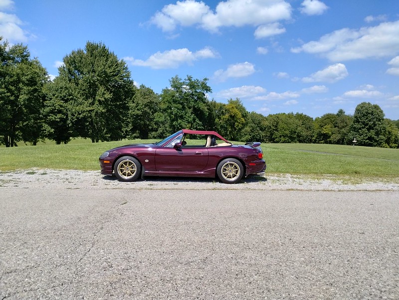
Well, time to go back to work. I was off longer than normal this time due to health reasons, but the doctors gave me the green light so off I go. She got a final bath this morning and I took a nice little fun drive afterwards,
There won’t be any posts until I get home again down the road, but stay tuned!
Sail on sailor.,Well, time to go back to work. I was off longer than normal this time due to health reasons, but the doctors gave me the green light so off I go. She got a final bath this morning and I took a nice little fun drive afterwards,
There won’t be any posts until I get home again down the road, but stay tuned!


