This is a howto expansion on this excellent post. I just followed his instructions and completed the process, and I found myself wishing for some detailed photos, so here are some shots I took as I was wiring my headlights. My highs and lows work now.
The side markers in the headlight assembly still aren't lighting up because nothing is connected to them. Can I wire them in parallel to the front clip side marker in my car? Might be overkill. Might snap the fuse.
Anyway here are some photos of the tools I used and how I wired it all up.
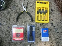
You will need:
1. pliers to crimp things with.
2. something to cut wire with
3. a wire stripper (not your teeth, rambo)
4. some mini screwdrivers are nice
5. 2x Sorenson MR78 relays
6. 2x H4 connectors. the ones I bought were crappy but seem to work.
You can see some of this stuff pictured here:
<a href="attachment.php?attachmentid=115760" target="_blank" ><img class="thumbnail" src="attachment.php?attachmentid=115760&stc=1&thumb=1" border="0" alt="Click image for larger version
Name: IMG_0046.jpg
Views: 1
Size: 86.8 KB
ID: [ARG:4 UNDEFINED]" /></a>
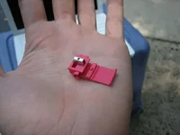
I also used these 3M splicer thingies pictured here, but I forgot where I got them. They are great for letting you not cut off the OEM connector and not destroy the wire to them but still get power spliced into them.
<a href="attachment.php?attachmentid=115761" target="_blank" ><img class="thumbnail" src="attachment.php?attachmentid=115761&stc=1&thumb=1" border="0" alt="Click image for larger version
Name: IMG_0048.jpg
Views: 1
Size: 35.2 KB
ID: [ARG:4 UNDEFINED]" /></a>
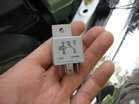
And here's the relay in question:
<a href="attachment.php?attachmentid=115762" target="_blank" ><img class="thumbnail" src="attachment.php?attachmentid=115762&stc=1&thumb=1" border="0" alt="Click image for larger version
Name: IMG_0050.jpg
Views: 2
Size: 42.0 KB
ID: [ARG:4 UNDEFINED]" /></a>
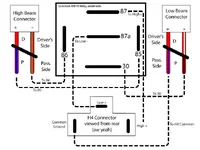
Here's a slightly more detailed drawing, based on thewrench's information that you may find helpful.
<a href="attachment.php?attachmentid=115765" target="_blank" ><img class="thumbnail" src="attachment.php?attachmentid=115765&stc=1&thumb=1" border="0" alt="Click image for larger version
Name: protege5-relay.jpg
Views: 0
Size: 44.8 KB
ID: [ARG:4 UNDEFINED]" /></a>
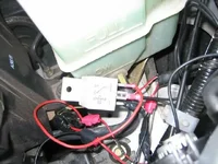
And here's what my sloppy finished product looks like on the driver's side.
<a href="attachment.php?attachmentid=115764" target="_blank" ><img class="thumbnail" src="attachment.php?attachmentid=115764&stc=1&thumb=1" border="0" alt="Click image for larger version
Name: IMG_0052.jpg
Views: 3
Size: 62.3 KB
ID: [ARG:4 UNDEFINED]" /></a>
I taped everything up to avoid having moisture problems, and hid it all away as best I could. On the driver's side I figured it was best not to have the relay and wires laying on the radiator hosts which are all around, and on the pass. side there is a pully and belt situation that it would be bad to have your wires get into.
So that's that! Now I have high beams and low beams in my MSP headlights on my Protege. Now to get the pesky Driver's side turn signals to work and I'm all good!
Attachments
Last edited:

