OK, well I did mine! Using a regular T1 LED (since that's what I had) and NO extra wires. Again, a big thanks to
brchan for leading the way!
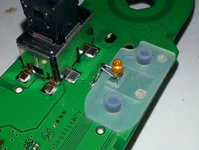
I bent the LED wires such that they'd fit around the switch membrane without needing to cut it. I soldered the anode 'leg' to the PCB patch & trace that leads to the 'pink square' connector pin in brchan's earlier photo. I then scratched an area of the ground plane clean and soldered the other, cathode, leg to that. Picture worth a thousand words (note the heatshrink insulation on the anode leg):
This is the LED with the membrane reattached:
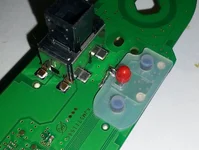
Then I soldered a regular 1/3 watt resistor directly across the 'yellow square' (+12V supply) and 'pink square' (LED anode) connector pins in brchan's photo - see the yellow and pink arrows below:
I started with a 5100 ohm resistor to test the LED brightness compared to the existing window switch backlight. With the LED I used it was still too bright, but I also saw that although it was a deep amber LED, it was
not as deep as the existing backlight color. So I found a red rice-bulb 'condom' (for coloring tiny incandescent lamps) that I'd taken off something else and stuck it over the LED. That made the resulting color PERFECT, but dimmed the output considerably, so I ended up having to go DOWN to a 3300 ohm resistor instead, to match both color AND intensity.
")
Just as a note, if you do this the preferred way, with an 0805 surface mount LED, you can still avoid long wires. Just bridge the end of the cathode trace to the ground plane alongside it, with either a solder blob, or short bare wire. Then use the regular radial wire resistor like I did.
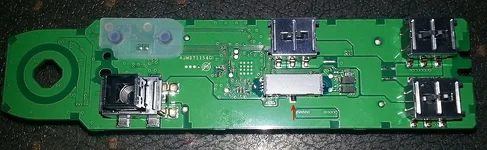
Note 2: Further to brchan's "auto-up/down reset" tip above... When you put the PCB back into the switch box, first make SURE the driver-window Hall-effect (slider) switch is in the CENTER position. You can easily knock it out of place when handling the board, and if so, the driver window plastic button won't engage and your driver window won't go up and down
at all! See red arrow below: