Setting up your AEM engine management

ddogg777

Member
:
2002 Yellow P5
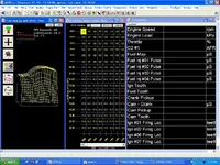
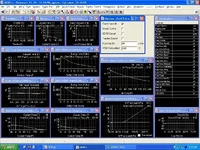
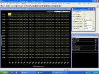
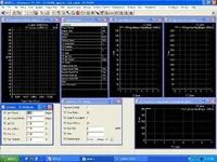
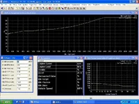
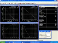
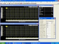
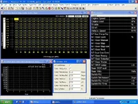
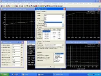
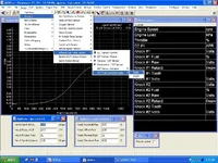
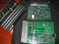
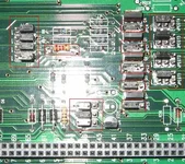
A few months ago, Beau at Mental Addiction Motorsports decided to avoid the hassle of setting up AEM units for every customer and post a how-to so that everyone can do set one up. I have taken it just a little bit farther so that it works more in congruence with our stock sensors. For all those who wish to set up the AEM 1050 box (for Hondas) for their 2002+ Protege5 MT, just follow along. I don't know what differences there are for other model Proteges so don't ask me. For those who have never seen the AEM, just visit their website, www.aempower.com, and you can see all their neat stuff. They even have a forum so that all the tuners can share their setups and ask questions. It has been invaluable seeing as that our car is not officially supported. I have had to spend long hours over there making sure I got everything right with my setup and I am happy to now share what I learned. I am not sponsored by AEM, so I am receiving nothing for this and don't bother calling them asking for tech support on our car because it isn't "officially" supported, but on their forums you can acquire great knowledge and help. First off I thought I'd post a few screenshots of what it can do. later I will take pictures of the internal mods that need to be done on the 1050 box (resistor change and jumper setup) and also the pinout so that you can enjoy it on your car. Attached is a zipped calibration that works for my RC550s injectors. It still needs tuning because I'm not really a tuner, more of an engineer...

Special thanks to Beau for his hard work, Steve at NSNmotorsports for helping me understand how our sensors work with our stock ecu, and the guys on the AEM forums for their knowledge.

Use of my calibration is at your own risk. It is by no means a finished product.
 

Attachments

Last edited:
This is our 3d fuel maps and advanced fuel trims. You can set these up as a table or as a map. Every section has an advanced section that contains 'trims' or multipliers so that you can adjust fuel, ignition, boost control, idle control, pump control, etc...I will only post a couple...
 

Attachments

  • fuelmaps.webp
    fuelmaps.webp
    118.4 KB · Views: 368
  • fueltrims.webp
    fueltrims.webp
    165.7 KB · Views: 299
Last edited:
Here is a shot of the electronic boost control and traction control...
 

Attachments

  • boostcontrol.webp
    boostcontrol.webp
    147.1 KB · Views: 317
  • TC.webp
    TC.webp
    127.2 KB · Views: 274
Last edited:
This is our basic idle setup. There is also and advanced section for setting up stepper motors and PWM motors(not posted). And here is also a shot of the accel pump feature (also has decel and fuel cut too).
 

Attachments

  • idle.webp
    idle.webp
    120.7 KB · Views: 274
  • accelpump.webp
    accelpump.webp
    136.5 KB · Views: 246
Last edited:
Here you can set it up to trigger your solenoids if you have an automatic transmission (set your own points!). Or you can go to the nitrous map and set up for a shot of NNNOOOOSSSS!!!
 

Attachments

  • nitrous.webp
    nitrous.webp
    168.9 KB · Views: 241
  • auto.webp
    auto.webp
    140.9 KB · Views: 225
Last edited:
The first picture shows knock control in the background (it can support duel knock channels!) and all the other sensors that you can set up in the foreground (like EGT fuel correction!). I'm not familiar with the J&S, but I think the AEM can do all that it can do, like retard timing, add fuel, etc...The next picture shows the output configuration. They can be setup up to work with switches too!
 

Attachments

  • outputs.webp
    outputs.webp
    123.6 KB · Views: 234
  • egt_knock_control.webp
    egt_knock_control.webp
    123.8 KB · Views: 257
Last edited:
You must open up the AEM to make the necessary changes. This procedure may void your warranty. Be very careful in separating the two pcbs, gently rock the top pcb up and down until it works its way out (may take a minute). Then, make sure all the jumpers in the bottom pcb are set up as mine. Next, grab a 2200 ohm resistor and replace R4 on the bottom pcb. We have to do this because we are sharing weak crank signals with our stock ecu, this will increase the gain on the signal. Everything in red boxes in the 2nd picture should be the same as yours. You can now put it back together and begin your tedious wiring.
We will also have to wire in fast switching diodes on the two crank lines that feed the AEM so that the stock ecu doesn't receive feedback from it. You should wire the diodes so that only signal goes in, nothing out.
 

Attachments

  • aem1.webp
    aem1.webp
    156.8 KB · Views: 334
  • aem2.webp
    aem2.webp
    58 KB · Views: 341
Last edited:
Here is the revised pinout. You will cut each wire from the stock ecu and send it to the AEM, unless I say to share it. Or, you can do what I did and cut up an extension harness so that you don't have to cut any wires from the stock computer. If you do decide to cut into your car's harness, be sure to solder and shrink wrap every joint after you have triple-checked the pin numbers. You must do this in order to rule out any problems you might have. I can't stress this enough!(pissed)

Here you go!(first)

Stock Pin#/AEM pin#

2/A2
80/A16
96/A17
47/A20
45/A22
41/A27

71/B1 (share)
83/B1 (yes, that's right)
24/B2 (share)
101/B3
74/B4
100/B5
97/B9 (share)
51/B10 (share)
75/B11
26/B13
76/B20 (share)
55/B21 (share)
77/B22 (share)
54/B23

57/C3
59/C7
21/C8 (share with diode)
22/C9 (share with diode)
52/C12 (share)
Wideband/C16
MAPs/C17
MAP-/C18
MAP+/C19
58/C23 (share)
IAT/C25
38/C26
89/C27
85/C29
86/C30

90/D6
91/D9
Boost/D13 (1.5A max, connect to switched power if solenoid requires more)
Boost/D16

For engine coolant temp, throttle position, and MAF voltage to the stock ecu I made a simple breadboard (1"x1") and made reference voltages for each pin by sending 5V from the stock ecu (pin #90 wasn't being used any more; it's 5V and originally used for the sensors anyway). Through a combination of resistors you can send any voltage you want to the stock computer. You will have to do this so that the stock ecu is happy (no codes) and turns on the alternator. If you don't use your primary and secondary O2s, you can send voltages from this little breadboard as well so that it is happy. After I finished soldering the resistors, I melted hot glue over it to seal it up.
 
Last edited:
Yes hurry up! The main reason I am posting all this is so that we can all share calibrations. I am good at getting stuff to work, but I'm no tuner...(poke)
I have no idea what good timings and such are for the car...today I found out that running 13.5 afr at 14psi and 8 degrees timing is not good. I just now added some fuel and will be adjusting my timing maps.
 
awsome write up, I will sertanly be needing this after I get a refund from my credit card for the unit Beau was suppose to ship to me.

thanks
 
Wow, good work. Too bad i'm not keeping mine. Someone will find this VERY useful because i just sold mine...
 
Thanks this is some really great priceless info. and oh yeah 13.5 AFR at 14 psi is no good. Add fuel till you get to 11.5AFR accross the board at full throttle. Then gradually add timing to a max of 12deg. Pay attention to your knock activity in the data log. If it goes up significantly before you get to the 12deg stop and back it off. After those figures your on your own.
 
Thanks Blaine, sorry it took me so long to get all this posted, but I'm in grad school and don't even have time to see my car during the week. The latest calibration that I uploaded actually uses Steve's (NSNmotorsports) timing map and I did add a bunch more fuel up top. I still haven't had a chance to try it out but I'm sure it will be much nicer. Concerning the knock, I don't think my sensor is tightened properly because I don't see much change over 0.02V (or is it 0.2?), next time I try it I will do internal logging. Can you see knock voltage changes while pc logging?
 
I have a set of spare connectors just for such an occasion, I may even have enough crimp pins too. Did your AEM not come with connectors?
 
ddogg777 said:
I have a set of spare connectors just for such an occasion, I may even have enough crimp pins too. Did your AEM not come with connectors?

I just started trying to get one these to run right that was originally hooked by someone that had the instructions from Mental Addictions DIY AEM thread. It was wired with 22 AWG and all of the connectors that originally came with it are gone. Here is the link am not sure if they are what come with the kit http://aempower.com/ViewCategory.aspx?CategoryID=84 . It definitely needs some wiring help.
The two biggest thing I noticed with the car before it came back apart was a WOT the tachometer would jump to 6000 RPM initially and then go back to 3000 RPM the dyno really did not know what to do when this happened. And their also seemed to be no control over the IAC motor. The original map that came with it seemed to look way off no one scaled RPM and I think I going to try something besides a GM 3 bar since they are not known for good idle characteristics. The only thing I have noticed about your basemap that it seems to have alot of spark advance at lower RPM's(below 3000) under boost have you had any knock problems at WOT?
Does anyone know where to get the parts needed for the Ford connectors so this could be made a cleaner connection between the stock harness and the AEM?
 
Back