
After a bunch of research (and with the help of bagman1) I discovered that the Mz3 is wired for heated mirrors but that the option was never offered in the US. This walkthrough shows how to replace the mirror with the heated glass and wire everything up. The glass with the heating elements is about $41 per side and only requires you to add wiring between the glass and the mirror side of the wiring harness plug. All the rest of the wiring is already present in the car and once installed the mirrors come on with the rear defroster. This walkthrough will also work for the wide-angle heated glass sold by nabobery on ebay, however I chose to use the OEM glass.
I also took this opportunity to install a few LEDs in the bottom of the mirror mounts to act as puddle lamps when I unlock my doors. If you're not doing this then you can ignore those steps.")
Many thanks to billm and BiggBlunt from mazda 3 forums for their walkthroughs and suggestions on how to do these two mods.
Parts needed:
Supplies:
-Driver's side heated glass p/n BP8M-69-1G7
-Passenger's side heated glass p/n BP8M-69-1G1
-wire (approx 30")
-small spade connectors
-solder
-pack of diodes
-electrical tape/heat shrink
-small zip ties
-LED lights
Tools:
-phillips screwdriver
-8mm socket/wrench
-torx driver ('07+ models, not sure of the size)
-mini flathead screwdriver
-soldering iron
-drill (dremel, etc.)
-3/8" bit
-wire cutters/strippers/crimpers
Difficulty:
1-2 if you're comfortable with taking things apart and know how to solder/work with wiring. 4-5 if you've never done any wiring but can follow directions and are willing to learn to do new stuff. 8-10 if you don't know how and can't follow instructions.
Time required:
30 minutes per side if you're very quick, 45 minutes to an hour if you're slightly more methodical. Over an hour/side if you're taking pictures.
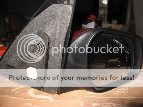
Start by removing your mirror from the car. Open the door and grab the back edge of the triangular panel housing the tweeter and pull towards the inside of the car to release it. Unplug the wiring harness plug and remove the three 8mm bolts holding the mirror to the car. Make sure to support the mirror since it will fall once the bolts are out.
 from BiggBlunt
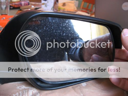
Now here's your mirror off of the car.
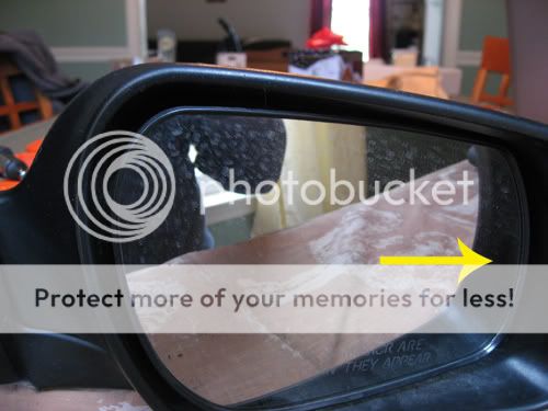
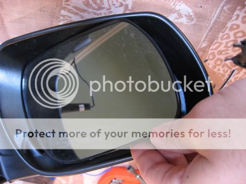
First remove the glass portion. The glass is held on by three ball joints, one large center one, and a small one to the outside and to the bottom of the large one. Push the glass all the way to the outside (the motor will make popping noises but that's okay). Then grab the inside edge of the mirror and pull towards you to release the center ball.
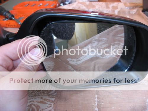
Next push the mirror all the way to the inside and grab the outside edge. Pull back firmly to release the small outside ball. Once that's loose push the mirror up and grab the bottom edge. Pull back to release the bottom/last ball joint. Set the mirror aside.
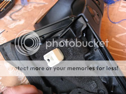
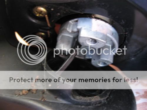
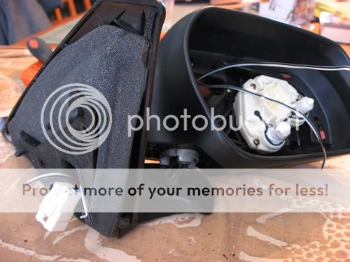
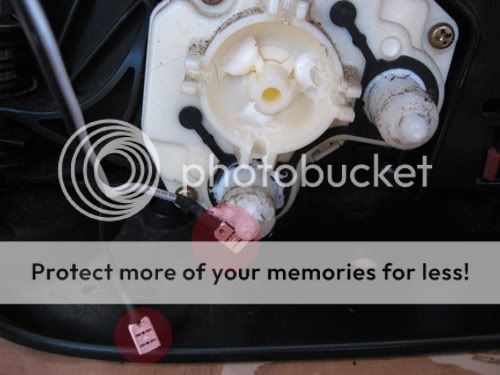
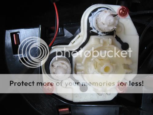
This is what the mirror motor looks like without the glass
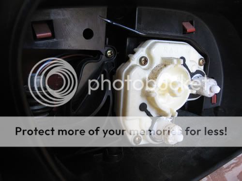
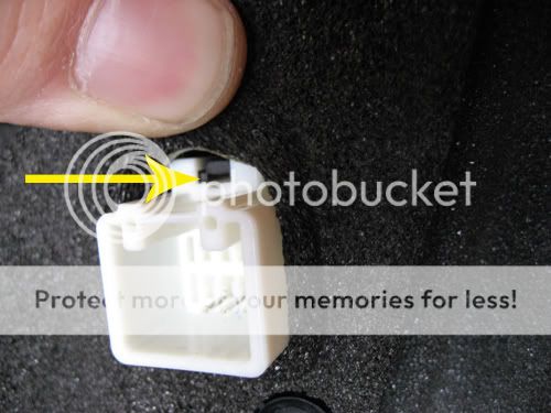
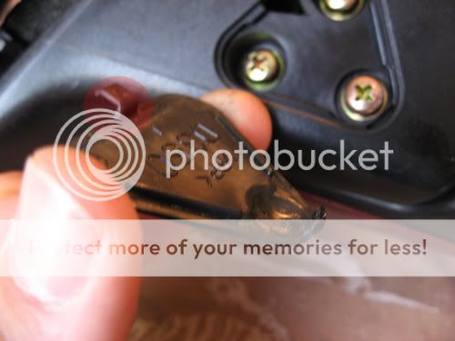
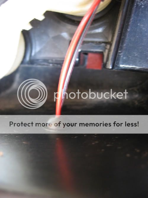
Next we have to release the white plug. Lift up the foam above the plug to reveal a little slot beneath a piece of black plastic. Insert a flathead screwdriver into the slot and push firmly down while pulling the plug out to release the little plastic tab holding it in place.
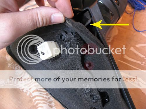
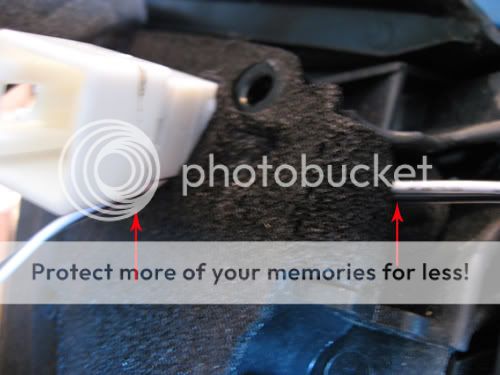
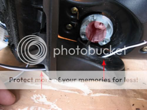
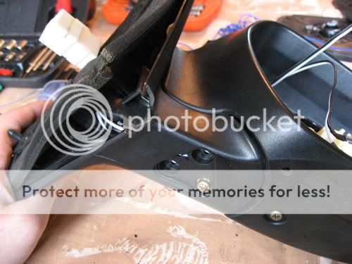
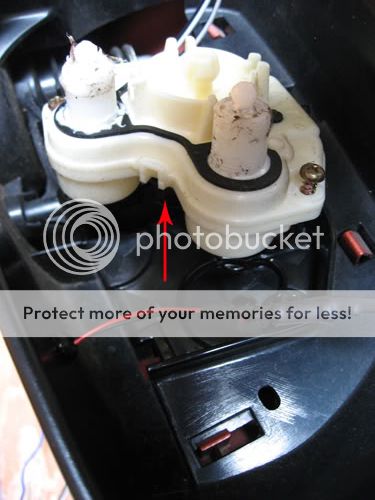
Flip the mirror upside down and pull the foam section from around the corner to run the wiring. Take care not to tear the highlighted sections. You don't have to fully remove it, just expose the bottom corner section.
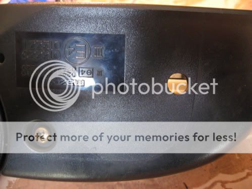
Remove the triangular panel by prying up the corner with the bulge. Try not to pry from any other part as it could break the clip on the opposite side.
Remove the three screws under the cover and then pull to separate the two sections. They won't pull very far because of the wiring inside, but it will be enough to let you run wires through it. '07 and newer models have torx head screws instead of phillips head screws. Mine is a '05 so I'm not sure of the size of the torx bit.
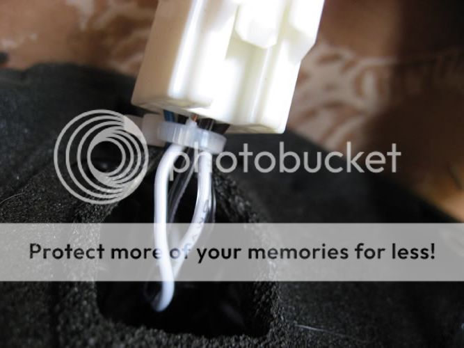
Time to start running wires. Start at the white plug and run the wire between the pieces of foam to come out where the rest of the OE wiring is. Then run the wire through the channel towards the hinge section. Once through to the hinge run the wiring up through the tube with the springs.
If you're installing LEDs then repeat the above procedure so you have two pairs of wires.
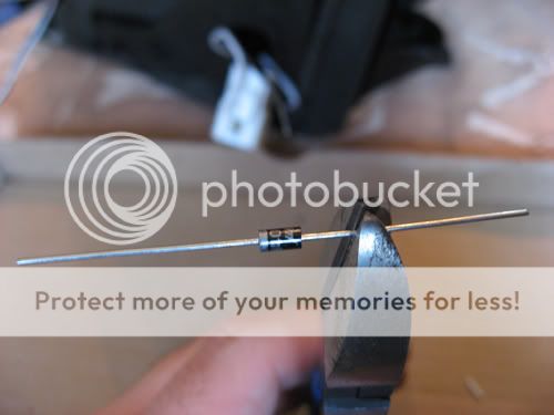
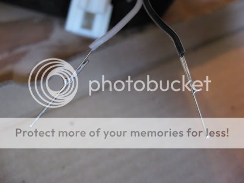
Now it's time to fabricate the new pins for the harness plug. Pull out your pack of diodes (it doesn't matter which ones you buy, just try to find ones that match the size of the pins in the plug) and cut the "legs" off of the diode. You need about an inch or so for each pin, but confirm the length by sticking it into the plug and matching the depth of the OE pins. Here's about how long I cut mine. The first time you'll probably want to cut it long as you can always trim it later if it sticks out to far.

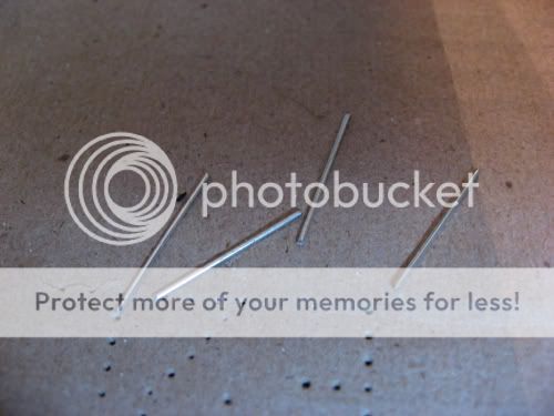
All the pins cut and ready to solder. Strip off the ends of the wires and tin them with solder, then solder the pins onto them.
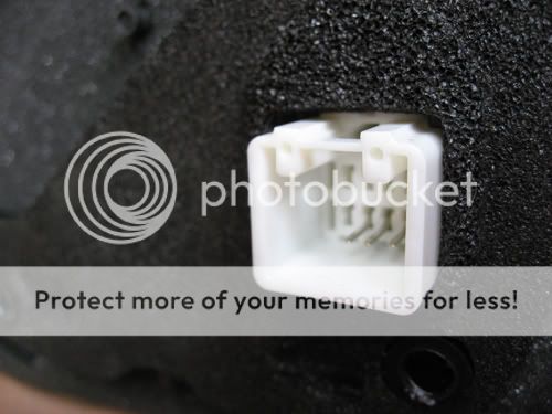
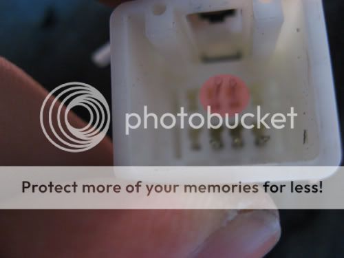
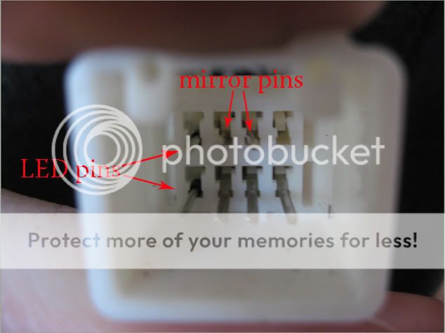
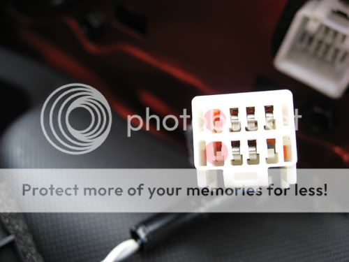
Now we insert the newly pinned wires into the white plug. We want them to come out of these two holes to match up with the green and black wires on the other side of the plug. If the pin/wire doesn't fit snugly in the hole then try adding a layer of heat shrink to give it a better hold. This is a good time to gauge the length of the pins you have and trim them down if they stick out too far. Don't worry about aligning them perfectly right now as we can take care of that later. If the pin/wire moves too much in the hole try putting a layer of heat shrink around the wire to snug it up a bit.
If you're installing LEDs then you can either insert more pins like I did or run a separate wire out like BiggBlunt I used the two empty slots to add more pins.
Once all your pins are in and the lengths are correct zip tie all the new wiring to the existing wires to keep them from moving around.
Trim off any excess wires on the other end and attach mini female spade connectors onto the ends of the mirror wiring.
Once done with that reassemble the two pieces of the mirror housing arranging the wires so they're not pinched anywhere in the process. Reinsert the white plug and replace the foam trim.
On to the LED installation. I used 4-chip white superflux LEDs from www.oznium.com. Determine where you want your LED to be placed and drill the hole to match your LED size. Test fit your LED to make sure it fits to your liking. The superflux's mount in a 3/8" hole, however I had to bore it out a bit to get it to fit very snugly. Mine ended up sitting slightly more flush than this once installed.
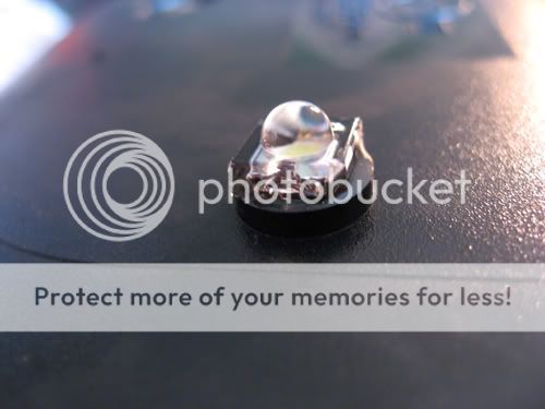
Once you're satisfied with the placement/fit apply some super glue the the sides of the hole and insert the LED. I also painted a bit of glue around the back of the LED once it was in place.
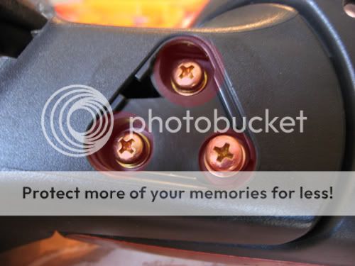
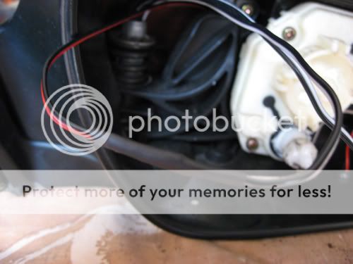
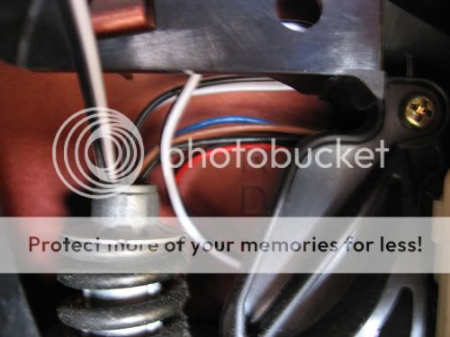
Now we run the LED wires behind the mirror motor to come out by the top of the tube with the spring. You may or may not have to remove the motor to do this. I was able to fish a wire behind the motor of one mirror and pull the wiring through, however I just couldn't get it to feed on the other side. Removing the motor however is as simple as unscrewing these three screws. Then just pull the motor forward slightly and run the wire behind it. Reattach the motor.
Connect the LED wiring to the wires going to the white plug and then tuck the excess wiring behind the black frame behind the motor.
Plug the heated glass into the spade connectors and reinstall the glass to the motor. First connect the large center ball. As hard as you have to push you'll feel like you're about to snap the glass in half but then you'll suddenly hear a loud pop and it will be connected. Do the same thing for both of the small ball connectors.
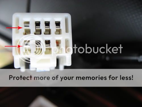
Now on to wiring up the car side of the plug. I opted to not run a separate wire from the mirror like BiggBlunt did because I'd rather have the mirror easy to remove. What I did was inserted new spring clips into two of the empty spots of the car side of the harness. I removed the spring clips from an old computer connector.
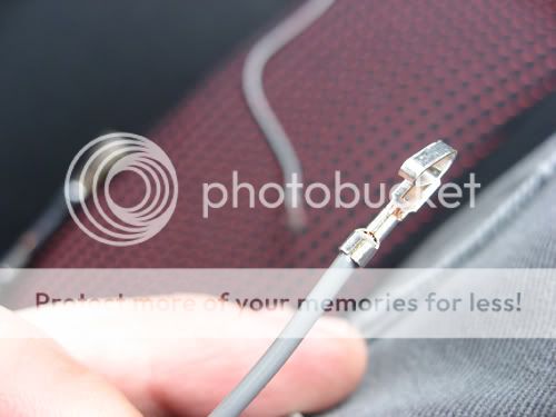
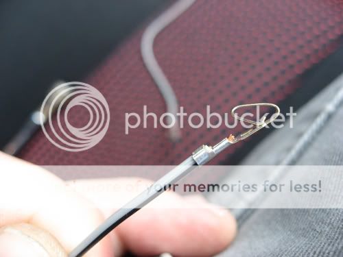
To line up with the pins I put on the mirror side of the plug I'm inserting the clips into these two spots. Just push the clips into the back of the slot and push it all the way it with a mini screwdriver. You can see the different shape of the new clips vs. the originals. Due to the shape I ended up angling the pins upward a bit so that instead of going into the hole like on the other slots they push against the top of it.
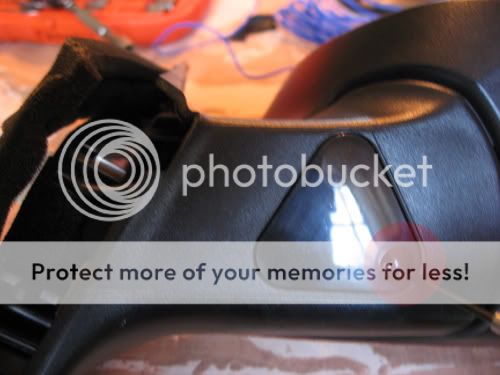
Now is when you take the time to make sure all of the pins are aligned properly. The diode legs are pretty bendable so you should be able to easily position them with a small flathead screwdriver. Reinsert the plug and test everything out. I haven't wired the LEDs to power yet, however they light up quite nicely when tested off my drill battery. Mostly I wanted to finish the mirror part of the install and get them back on my car so I could drive around. Here's the mirror on the car with the LED installed (no lit pics yet)

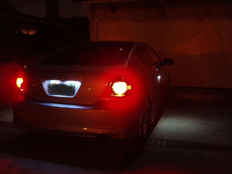
Here's a pic from www.oznium.com (to give you an idea) where someone did the same thing with a scion tC, except with the LEDs on the door handles.
I also took this opportunity to install a few LEDs in the bottom of the mirror mounts to act as puddle lamps when I unlock my doors. If you're not doing this then you can ignore those steps.
Many thanks to billm and BiggBlunt from mazda 3 forums for their walkthroughs and suggestions on how to do these two mods.
Parts needed:
Supplies:
-Driver's side heated glass p/n BP8M-69-1G7
-Passenger's side heated glass p/n BP8M-69-1G1
-wire (approx 30")
-small spade connectors
-solder
-pack of diodes
-electrical tape/heat shrink
-small zip ties
-LED lights
Tools:
-phillips screwdriver
-8mm socket/wrench
-torx driver ('07+ models, not sure of the size)
-mini flathead screwdriver
-soldering iron
-drill (dremel, etc.)
-3/8" bit
-wire cutters/strippers/crimpers
Difficulty:
1-2 if you're comfortable with taking things apart and know how to solder/work with wiring. 4-5 if you've never done any wiring but can follow directions and are willing to learn to do new stuff. 8-10 if you don't know how and can't follow instructions.
Time required:
30 minutes per side if you're very quick, 45 minutes to an hour if you're slightly more methodical. Over an hour/side if you're taking pictures.
Disclaimer. This How To is for informational purposes only. I take no responsibility for any damage caused to your vehicle while you attempt this install. Be safe and have fun.
Start by removing your mirror from the car. Open the door and grab the back edge of the triangular panel housing the tweeter and pull towards the inside of the car to release it. Unplug the wiring harness plug and remove the three 8mm bolts holding the mirror to the car. Make sure to support the mirror since it will fall once the bolts are out.
Now here's your mirror off of the car.
First remove the glass portion. The glass is held on by three ball joints, one large center one, and a small one to the outside and to the bottom of the large one. Push the glass all the way to the outside (the motor will make popping noises but that's okay). Then grab the inside edge of the mirror and pull towards you to release the center ball.
Next push the mirror all the way to the inside and grab the outside edge. Pull back firmly to release the small outside ball. Once that's loose push the mirror up and grab the bottom edge. Pull back to release the bottom/last ball joint. Set the mirror aside.
This is what the mirror motor looks like without the glass
Next we have to release the white plug. Lift up the foam above the plug to reveal a little slot beneath a piece of black plastic. Insert a flathead screwdriver into the slot and push firmly down while pulling the plug out to release the little plastic tab holding it in place.
Flip the mirror upside down and pull the foam section from around the corner to run the wiring. Take care not to tear the highlighted sections. You don't have to fully remove it, just expose the bottom corner section.
Remove the triangular panel by prying up the corner with the bulge. Try not to pry from any other part as it could break the clip on the opposite side.
Remove the three screws under the cover and then pull to separate the two sections. They won't pull very far because of the wiring inside, but it will be enough to let you run wires through it. '07 and newer models have torx head screws instead of phillips head screws. Mine is a '05 so I'm not sure of the size of the torx bit.
Time to start running wires. Start at the white plug and run the wire between the pieces of foam to come out where the rest of the OE wiring is. Then run the wire through the channel towards the hinge section. Once through to the hinge run the wiring up through the tube with the springs.
If you're installing LEDs then repeat the above procedure so you have two pairs of wires.
Now it's time to fabricate the new pins for the harness plug. Pull out your pack of diodes (it doesn't matter which ones you buy, just try to find ones that match the size of the pins in the plug) and cut the "legs" off of the diode. You need about an inch or so for each pin, but confirm the length by sticking it into the plug and matching the depth of the OE pins. Here's about how long I cut mine. The first time you'll probably want to cut it long as you can always trim it later if it sticks out to far.
All the pins cut and ready to solder. Strip off the ends of the wires and tin them with solder, then solder the pins onto them.
Now we insert the newly pinned wires into the white plug. We want them to come out of these two holes to match up with the green and black wires on the other side of the plug. If the pin/wire doesn't fit snugly in the hole then try adding a layer of heat shrink to give it a better hold. This is a good time to gauge the length of the pins you have and trim them down if they stick out too far. Don't worry about aligning them perfectly right now as we can take care of that later. If the pin/wire moves too much in the hole try putting a layer of heat shrink around the wire to snug it up a bit.
If you're installing LEDs then you can either insert more pins like I did or run a separate wire out like BiggBlunt I used the two empty slots to add more pins.
Once all your pins are in and the lengths are correct zip tie all the new wiring to the existing wires to keep them from moving around.
Trim off any excess wires on the other end and attach mini female spade connectors onto the ends of the mirror wiring.
Once done with that reassemble the two pieces of the mirror housing arranging the wires so they're not pinched anywhere in the process. Reinsert the white plug and replace the foam trim.
On to the LED installation. I used 4-chip white superflux LEDs from www.oznium.com. Determine where you want your LED to be placed and drill the hole to match your LED size. Test fit your LED to make sure it fits to your liking. The superflux's mount in a 3/8" hole, however I had to bore it out a bit to get it to fit very snugly. Mine ended up sitting slightly more flush than this once installed.
Once you're satisfied with the placement/fit apply some super glue the the sides of the hole and insert the LED. I also painted a bit of glue around the back of the LED once it was in place.
Now we run the LED wires behind the mirror motor to come out by the top of the tube with the spring. You may or may not have to remove the motor to do this. I was able to fish a wire behind the motor of one mirror and pull the wiring through, however I just couldn't get it to feed on the other side. Removing the motor however is as simple as unscrewing these three screws. Then just pull the motor forward slightly and run the wire behind it. Reattach the motor.
Connect the LED wiring to the wires going to the white plug and then tuck the excess wiring behind the black frame behind the motor.
Plug the heated glass into the spade connectors and reinstall the glass to the motor. First connect the large center ball. As hard as you have to push you'll feel like you're about to snap the glass in half but then you'll suddenly hear a loud pop and it will be connected. Do the same thing for both of the small ball connectors.
Now on to wiring up the car side of the plug. I opted to not run a separate wire from the mirror like BiggBlunt did because I'd rather have the mirror easy to remove. What I did was inserted new spring clips into two of the empty spots of the car side of the harness. I removed the spring clips from an old computer connector.
To line up with the pins I put on the mirror side of the plug I'm inserting the clips into these two spots. Just push the clips into the back of the slot and push it all the way it with a mini screwdriver. You can see the different shape of the new clips vs. the originals. Due to the shape I ended up angling the pins upward a bit so that instead of going into the hole like on the other slots they push against the top of it.
Now is when you take the time to make sure all of the pins are aligned properly. The diode legs are pretty bendable so you should be able to easily position them with a small flathead screwdriver. Reinsert the plug and test everything out. I haven't wired the LEDs to power yet, however they light up quite nicely when tested off my drill battery. Mostly I wanted to finish the mirror part of the install and get them back on my car so I could drive around. Here's the mirror on the car with the LED installed (no lit pics yet)
Here's a pic from www.oznium.com (to give you an idea) where someone did the same thing with a scion tC, except with the LEDs on the door handles.
Last edited: